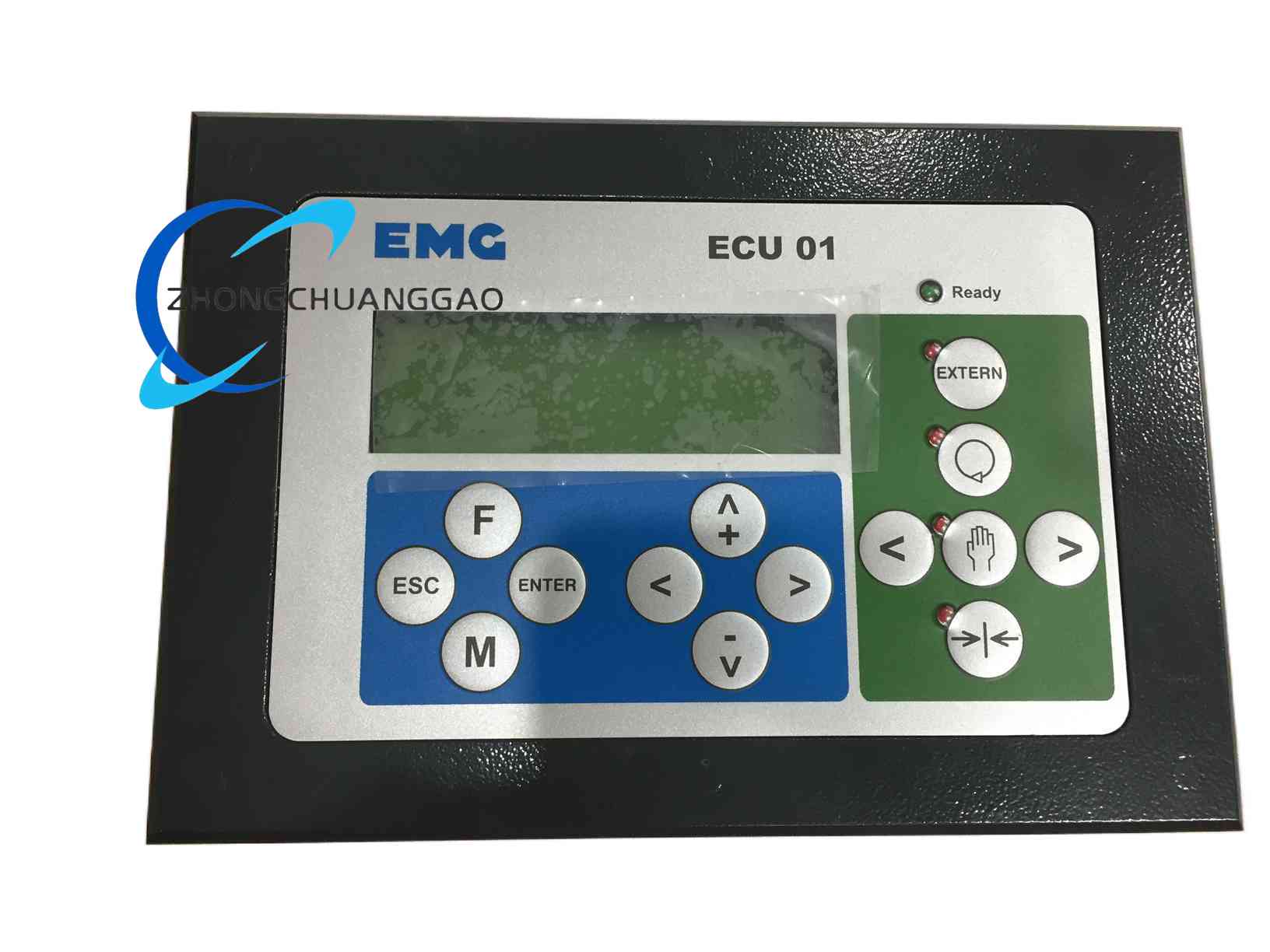
Technical Specifications
Engine speed control version: supply 8-35 VDC, magnetic pickup speed input, actuator or proportional solenoid output.
Signal/filter version: 0-10 VDC output, 4-20 mA output, configurable low-pass, high-pass or band-pass filtering, cutoff 1 Hz to 10 kHz according to configuration.
Communication: RS485 Modbus RTU in signal-version configurations; CANopen optional according to version.
Output accuracy: voltage output approximately ±0.1%, current output approximately ±0.2% according to filter and output configuration.
Response time: below 10 ms according to filtering setup.
Functional Features
Engine version stabilizes RPM under changing load, provides start fuel control and actuator damping.
Signal version suppresses noise through digital filtering and provides isolated analog outputs.
Both versions support industrial cabinet installation and standard control wiring.
Configurable parameters reduce manual calibration time during commissioning.
Performance Parameters
Engine version operating temperature: -20°C to +70°C according to typical governor documentation.
Signal version dimensions: approximately 110 mm × 90 mm × 40 mm for panel-mount configuration.
Protection: IP20 standard panel version; IP65 optional sealed enclosure according to version.
EMC: signal version complies with EN 55032 Class B and EN 61000-6-2/6-3 according to documented configuration.
Material Composition
Industrial control PCB with microcontroller or DSP.
Engine version includes sensor interface, actuator driver and tuning components.
Signal version includes analog input stage, filtering processor, DAC output stage and communication transceivers.
Enclosure: panel-mount housing or sealed industrial enclosure according to version.
Structural Features
Compact controller housing with sensor/actuator or analog I/O terminals.
Setup interface through onboard switches, software or communication port according to version.
Status indicators for power and operation according to manufacturer configuration.
Working Principle
Engine version measures engine speed from the magnetic pickup, compares actual speed with the setpoint and adjusts actuator current to increase or decrease fuel. Signal version samples the analog input, applies the selected digital filter, converts the result to 0-10 V or 4-20 mA output and transmits processed values over RS485 or CANopen when communication is enabled.
Installation Requirements
Confirm whether the unit is ordered as engine governor or analog signal regulator before installation.
Engine version requires shielded magnetic pickup cable and correctly polarized actuator wiring.
Signal version requires shielded analog input and RS485 cables with proper grounding.
Mount in a ventilated control cabinet away from high-voltage switching devices.
Use 24 VDC or 8-35 VDC supply strictly according to the delivered version.
Usage Precautions
Do not connect magnetic pickup settings to analog signal-input terminals or vice versa.
Set filter type and cutoff only after identifying sensor noise and control bandwidth.
Verify actuator current rating before connecting engine fuel devices.
Prevent reverse polarity on DC supply.
Calibrate speed gain, stability and droop under no-load and step-load conditions for engine applications.