Technical Specifications
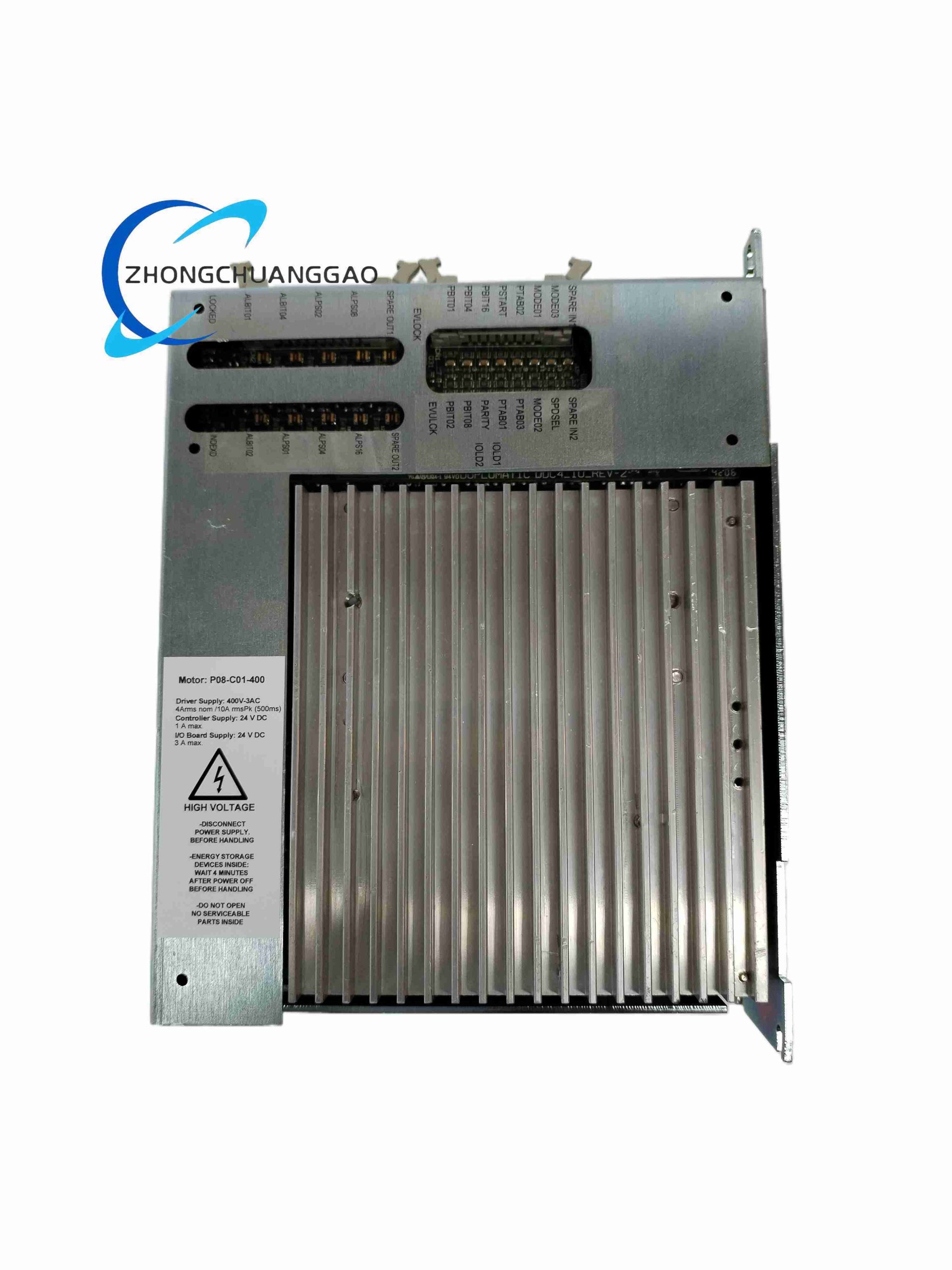
Model structure: DDC4 series electronic driver, 10 representing driver/class parameter, 400 representing supply or pressure class according to order code, 20 representing additional configuration according to order code.
Command input: 0-10 V, ±10 V or 4-20 mA according to configuration.
Output: regulated current to proportional solenoid(s).
Mounting: Euro-card format or DIN-rail enclosure according to version.
Valve compatibility: Duplomatic proportional directional, pressure and flow valves.
Functional Features
Converts analog reference signal into controlled solenoid drive current.
Supports proportional direction control with adjustable ramp and gain.
Provides current regulation instead of fixed voltage drive for stable valve performance.
Allows zero, span, ramp and dither adjustments according to card version.
Reduces dead-band and hysteresis effects in proportional hydraulic valves.
Performance Parameters
Output current follows command input after calibration.
PWM or regulated DC drive maintains solenoid current against coil temperature changes.
Dither setting reduces stiction and improves valve repeatability.
Response depends on valve size, solenoid inductance and card adjustment.
Material Composition
Industrial control PCB with power stages and signal conditioning circuits.
SCR or transistor/PWM output devices according to card version.
Metal or molded enclosure according to Euro-card or DIN-rail version.
Screw terminals or card-edge connectors for command and solenoid wiring.
Structural Features
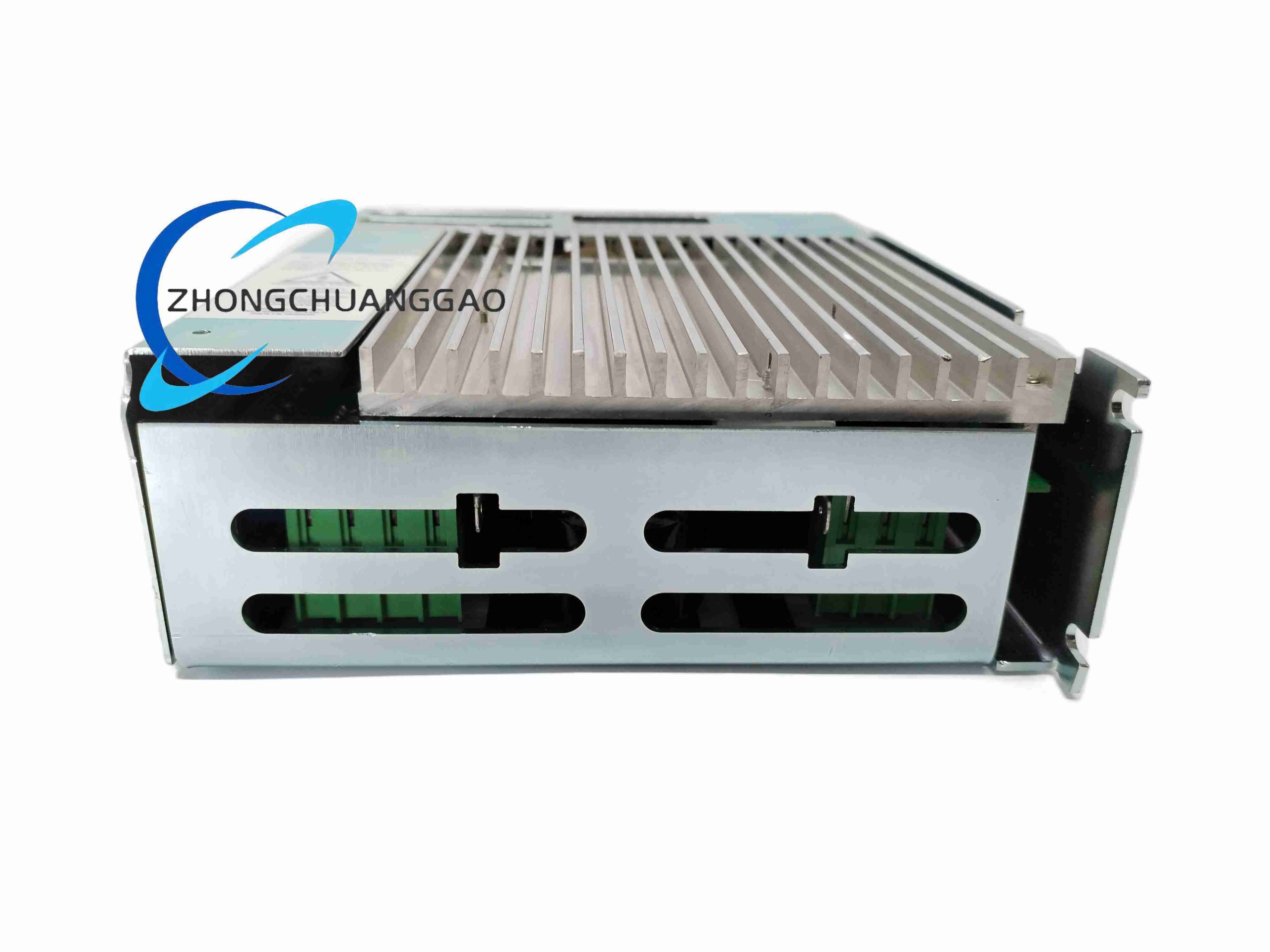
Compact driver housing suitable for control cabinet installation.
Separated power, command and solenoid terminal sections.
Front or onboard adjustments for zero, gain, ramp and dither.
Status or signal markings according to manufacturer version.
Working Principle
The card receives an analog command and generates a controlled current reference for the valve solenoid. Current feedback in the output stage maintains actual solenoid current equal to the commanded value. The magnetic force in the valve moves the spool or poppet proportionally, changing hydraulic flow path, pressure or directional state.
Installation Requirements
Install in a dry control cabinet with protection against vibration and contamination.
Match supply voltage, valve solenoid rating and command signal type before wiring.
Use shielded cable for command input and separate it from power cables.
Provide adequate cabinet cooling for continuous solenoid drive current.
Follow Duplomatic valve sheet for solenoid identifiers, polarity and current limits.
Usage Precautions
Do not connect solenoids with ratings above the card output specification.
Verify 0-10 V, ±10 V or 4-20 mA command configuration before startup.
Prevent short circuits on solenoid outputs.
Adjust ramp and dither only with the hydraulic system in safe state.
If the same model is used as CNC turret servo controller rather than hydraulic valve amplifier, request the valve/proportional amplifier order code separately because 400 VAC servo and 24 VDC turret versions have different power stages.