Technical Specifications
Axis quantity: 24 independent servo/stepper axes.
Command output: differential step pulse and differential direction signal per axis.
Maximum step frequency: 1 MHz per axis.
Feedback inputs: 24 isolated fault/ready/limit channels.
Fault input type: sink/source jumper-configurable.
Axis enable: 24 isolated solid-state enable outputs.
Controller bus: dedicated PMAC/PMAC-2 differential expansion communication.
Supply voltage: 24 V DC nominal, 18 V to 30 V operating range.
Full-load power: 12 W maximum.
Galvanic isolation: 2500 VDC between controller side and drive side.
Emergency-stop response: full axis disable within 0.5 ms.
Step output drive: 20 mA differential source/sink per channel.
Ingress protection: IP20 for enclosed cabinet installation.
Operating temperature: 0 °C to +55 °C.
Storage temperature: -40 °C to +85 °C.
Functional Features
Independent differential step/direction generation for all 24 axes.
Slew-rate-shaped output drivers to reduce EMI.
Optocoupler isolation between PMAC logic and servo amplifier power circuits.
Per-axis LED status for step activity, direction, fault, ready, and enable.
Global emergency-stop input that disables all axis outputs.
Jumper-selectable pull-up/pull-down termination for external drive compatibility.
Surge suppression on drive-side I/O using varistors and transient-suppression diodes.
Application Scenarios
Large-format multi-axis CNC systems.
Packaging and converting machines with numerous stepper axes.
Electronic assembly lines using 24 servo/steeper drives.
Printing, labeling, and web-handling systems.
Research motion platforms requiring centralized step/direction distribution.
Performance Parameters
Aggregate step throughput: 24 million pulses per second across all axes.
Step propagation delay: 120 ns or less per channel.
Fault capture latency: 80 ns or less.
MTBF: 520,000 operating hours at +25 °C cabinet temperature.
E-stop global disable execution: 0.5 ms or less.
Material Composition
FR4 industrial-grade printed circuit board.
High-speed optocouplers for all axis signal paths.
Solid-state drivers and solid-state relays for enable circuits.
Nickel-plated copper screw terminals.
UL94-V0 flame-retardant enclosure sections with steel reinforcement where rack-mounted.
Metal-oxide varistors and TVS diodes for surge protection.
Structural Characteristics
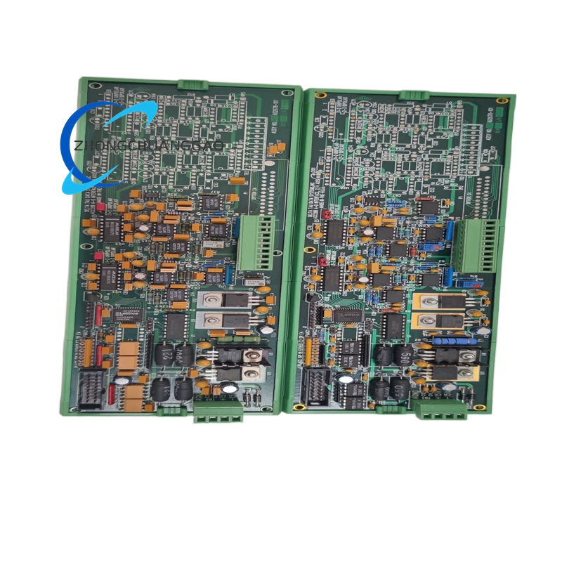
19-inch rack modular unit or 35 mm DIN-rail module according to build variant.
Separated controller-bus wiring zone and 24-axis drive wiring zone.
Dedicated hard-wire emergency-stop terminal isolated from communication bus.
Grounded shielding partitions between low-voltage logic and drive-side circuits.
Ventilated side panels for convection cooling in rack builds.
Lockable terminal ports to prevent vibration loosening.
Working Principle
PMAC sends trajectory and control data over the dedicated expansion bus to the interface processor. The processor generates shaped differential step and direction pulses for each axis and routes them to external servo or stepper amplifiers. Drive feedback such as fault, ready, and limit returns through isolated inputs. Enable logic and emergency-stop logic override output drivers, opening all axis command paths when safety conditions are triggered.
Installation Requirements
Mount in enclosed control cabinet on 35 mm DIN rail or standard 19-inch rack.
Apply 24 V DC with stable 18 V to 30 V range.
Segment controller-side and drive-side wiring into separate terminal zones.
Set sink/source jumpers according to amplifier feedback type.
Set step-output termination for the connected drive input impedance.
Ground the enclosure and shield motor/step cables to the same grounding bus.
Usage Precautions
Do not exceed 1 MHz step rate per axis unless the drive manufacturer confirms higher rates.
Verify optocoupler isolation before measuring resistance between controller and drive grounds.
Test emergency-stop disable functionally before production startup.
Prevent prolonged operation above +55 °C cabinet temperature.
Inspect terminal torque periodically in high-vibration installations.