Technical Specifications
Front size 72 × 72 mm. Panel cut-out approximately 68 × 68 mm. Auxiliary supply typically 24 VDC or 85–264 VAC depending on variant. Voltage inputs via VT/PT, current inputs via 5 A CT. Communication RS-485 Modbus RTU on communication/pulse variants. Operating temperature typically -10 to +55 °C.
Functional Features
Measures voltage, current, active power, and related electrical quantities. Digital display for fast reading. CT/VT ratio configuration. Pulse or alarm output on selected variants. Modbus communication for SCADA or BMS integration.
Application Scenarios
Genset control panels. Marine and offshore switchboards. Industrial motor control centers. Commercial building distribution boards. Retrofit projects replacing analog 72 mm meters.
Performance Parameters
Suitable for low-voltage and medium-voltage metering through external CT/VT. RS-485 Modbus RTU for polling by PLC, SCADA, or energy management system. Compact depth for dense panels.
Material And Structure
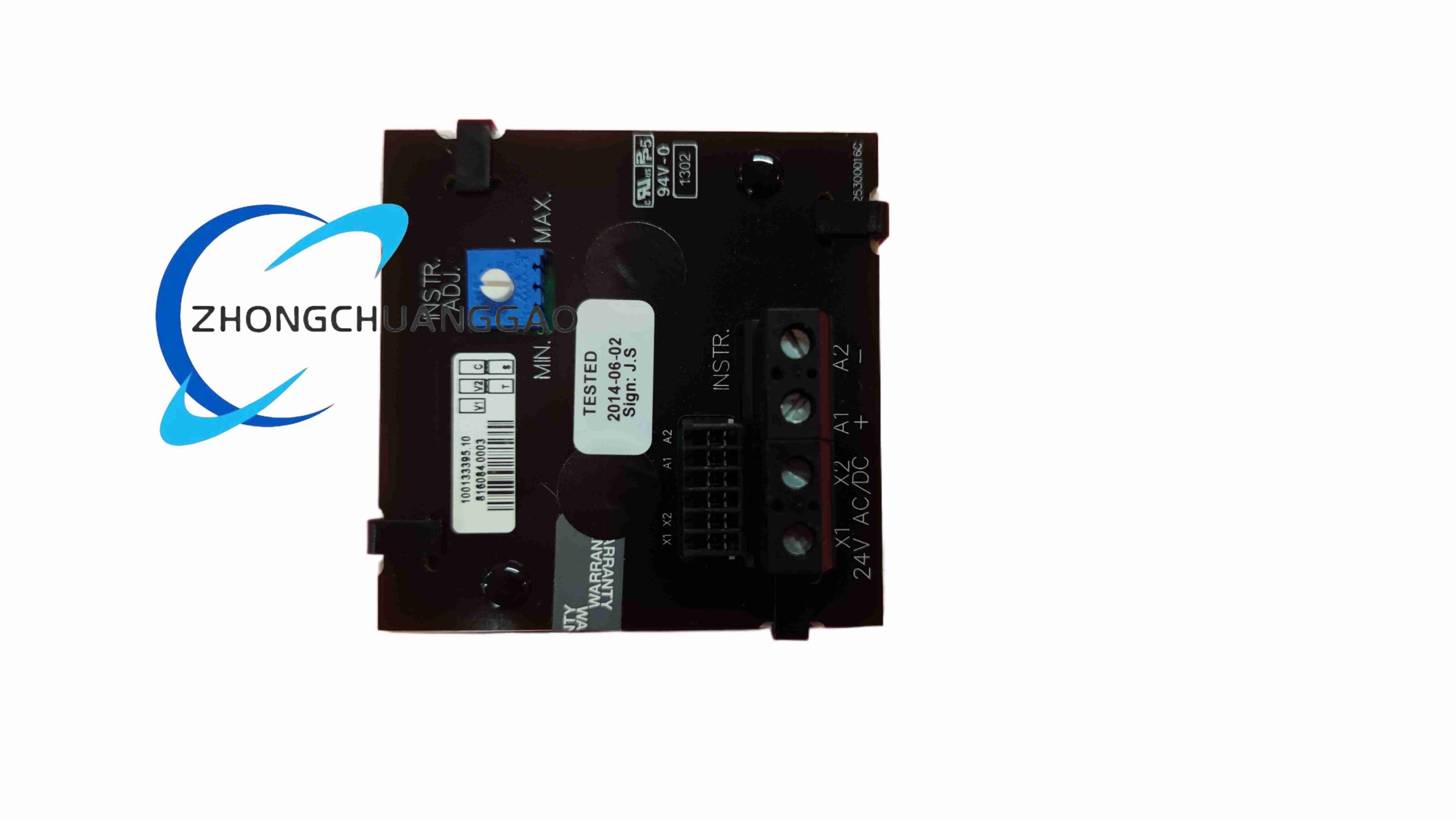
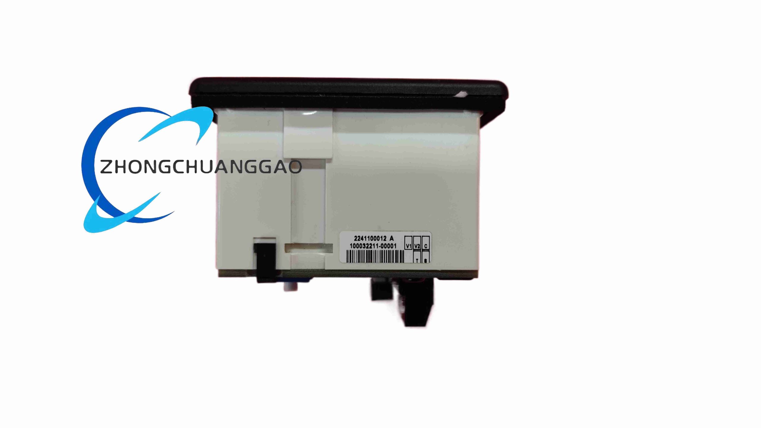
Plastic or industrial-grade front bezel. Rear terminal block. Internal measurement and communication electronics. Panel-mounted body with clamp/fastener fixing.
Working Principle
Voltage and current signals are scaled through VT/CT inputs, converted and processed internally, then displayed on the front panel. Data can be transmitted over RS-485 Modbus RTU to upper systems. Pulse or relay output can be used for energy pulsing or limit alarm.
Installation Requirements
Install in clean, dry switchboard with adequate ventilation. Use standard 68 × 68 mm cut-out. Maintain CT polarity. Short CT secondaries during installation if required. Use shielded twisted pair for RS-485 with proper grounding and termination.
Usage Precautions
Verify auxiliary supply before powering. Do not open live terminals. Check CT wiring to avoid open-circuit danger. Confirm Modbus baud rate, parity, and slave ID before communication. Calibrate CT/PT ratio in software before commissioning.