Technical Specifications
Auxiliary supply 8–36 V DC. Generator voltage input 100–600 V AC standard and up to 690 V AC according to configuration. Current input 1 A or 5 A CT. Protection functions include over/under voltage, over/under frequency, reverse power, overcurrent, phase-sequence and phase-loss detection, and emergency-stop monitoring. Communication RS485 Modbus RTU and CAN J1939. Built-in synchronizing logic with voltage, frequency and phase-angle matching. kW and kVAr load-share control. Event logging and diagnostics. Panel-mount construction with approximate depth 60 mm. Weight under 2 kg. Operating temperature −20°C to +70°C.
Functional Features
Automatic mains-failure transfer. Breaker control and synchrocheck. Parallel running with kW/kVAr sharing. Modbus and CAN integration with SCADA, PLC and engine ECU. Detailed event log for fault analysis.
Application Scenarios
Data centers and hospitals with no-break transfer. Industrial plants with multiple gensets. Utility and independent power producer peak-shaving. Water and wastewater facilities with remote Modbus monitoring.
Performance Parameters
Wide CT/PT metering. Full protection suite 27/59, 81, 32, 50/51 and phase-fault functions. RS485 and CAN communication. Synchronizing, import/export and load-shedding control.
Material Composition
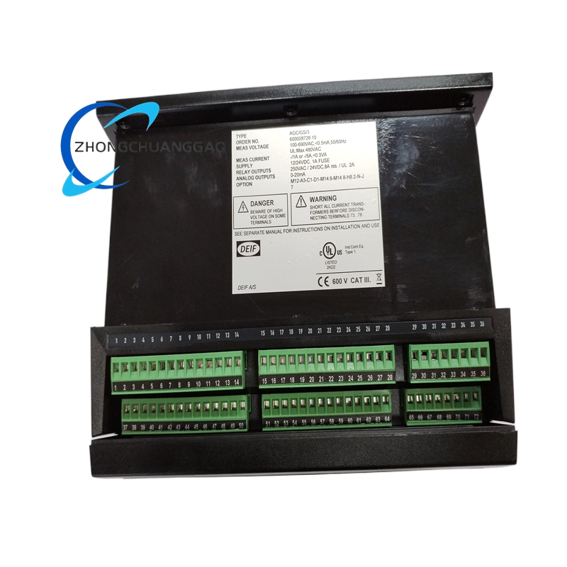
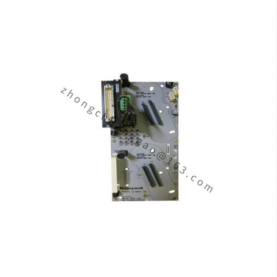
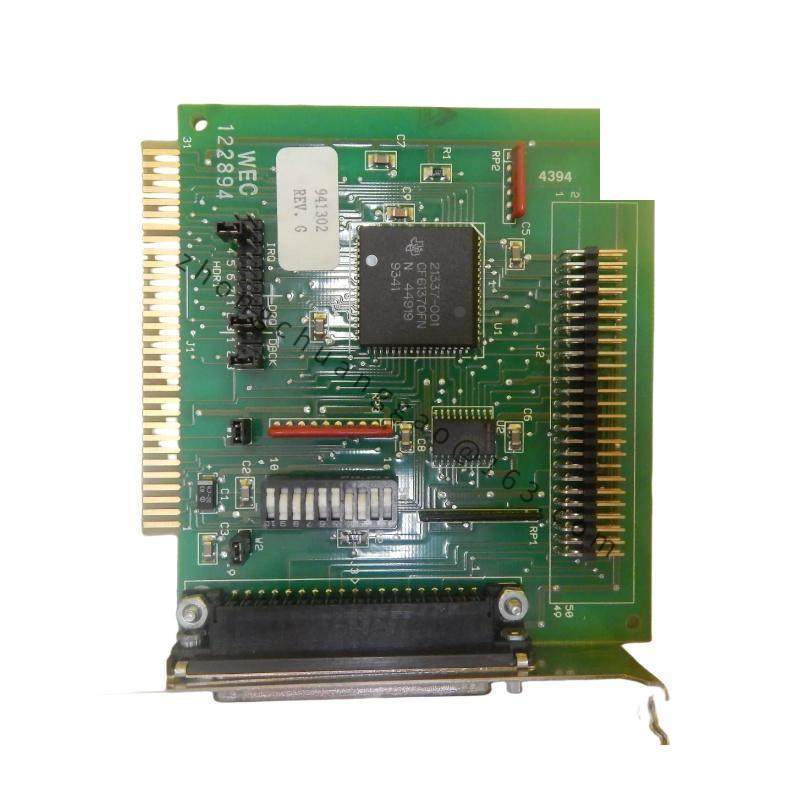
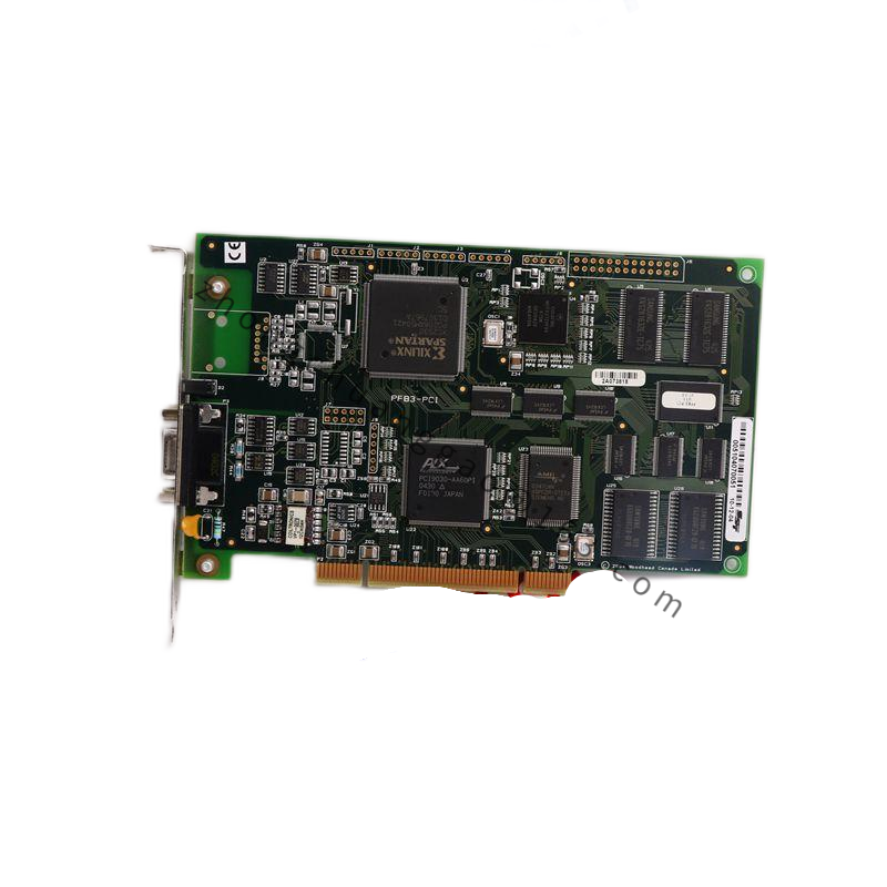
Switchboard-grade front housing. Measurement, protection and communication PCB. Rear terminal block for CT, PT, digital I/O, breaker control and auxiliary supply.
Structural Characteristics
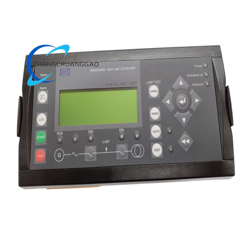
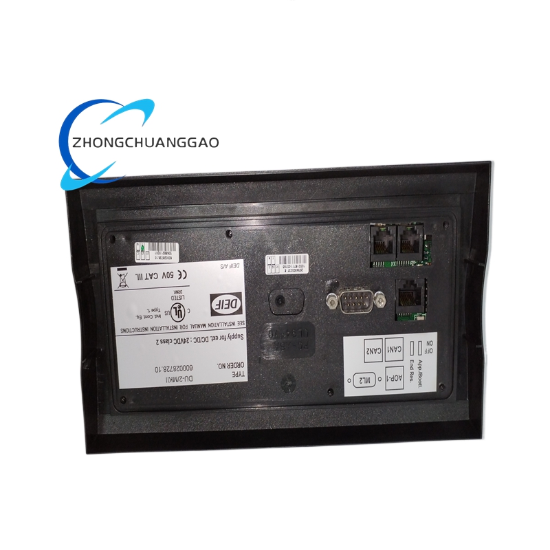
Panel-mount controller with display and programming interface. Separate metering inputs, protection relays, communication ports and synchronizing section.
Working Principle
Voltage, current, frequency and phase-angle measurements are evaluated against protection and synchronization setpoints. The controller adjusts speed and voltage references through governor and AVR interfaces or CAN ECU commands, closes the breaker when sync window is satisfied, and balances real and reactive power among parallel gensets.
Installation Requirements
Mount in a ventilated switchboard with stable 8–36 V DC auxiliary supply and proper fusing. Use shielded twisted-pair CT and PT wiring with correct polarity and phase sequence. Isolate communication cables from high-current power wiring. Ground the controller at a single point.
Usage Precautions
Verify CT polarity and PT phasing before energization. Test synchronizing window and breaker interlocks before live paralleling. Calibrate metering quarterly. Back up configuration and firmware before system changes.