Technical Specifications
Auxiliary supply 18–72 V DC for 24 V system variants and AC/DC variants according to order code. Generator voltage input up to 600 V AC line-to-line with PT support and up to 690 V AC on selected configurations. Current input 1 A or 5 A via CT. Measured values include voltage, current, frequency, power, energy and power factor. Protection functions for over/under voltage, over/under frequency, overcurrent, reverse power, overspeed, low oil pressure, high coolant temperature and start failure. Built-in synchronizing and sync-check functions. Load-sharing support through CAN with PCC 200 or plant controller. Communication RS485 Modbus RTU and CAN J1939 or CANopen. Graphical backlit display. Programmable digital inputs and outputs. Panel-mount construction. Operating temperature −20°C to +60°C.
Functional Features
Automatic mains-failure start. Automatic synchronization to bus or utility. Isochronous and droop load sharing. Full electrical and engine protection. Extensive metering on all phases. PC configuration through DEIF PC-Tool 200.
Application Scenarios
Marine auxiliary gensets. Offshore supply vessels and platforms. Hospital and data-center standby power. Industrial prime power and multiple-genset parallel operation.
Performance Parameters
Wide generator voltage sensing up to 690 V AC. CT input 1 A or 5 A. RS485 and CAN communication. Synchronization, protection and kW/kVAr management in one controller.
Material Composition
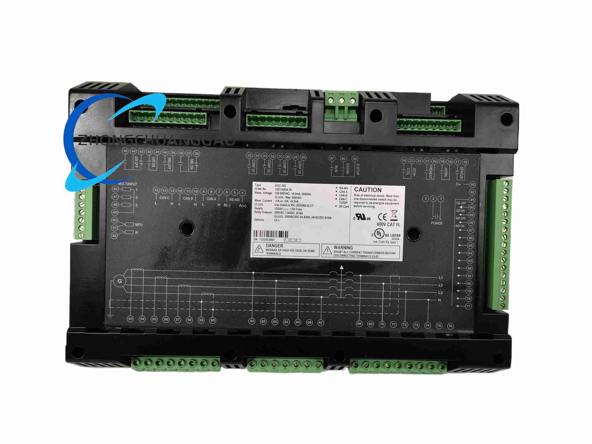
Front-panel display housing. Internal control PCB with measurement and communication interfaces. Rear terminal block assembly for CT, PT, digital I/O and power supply.
Structural Characteristics
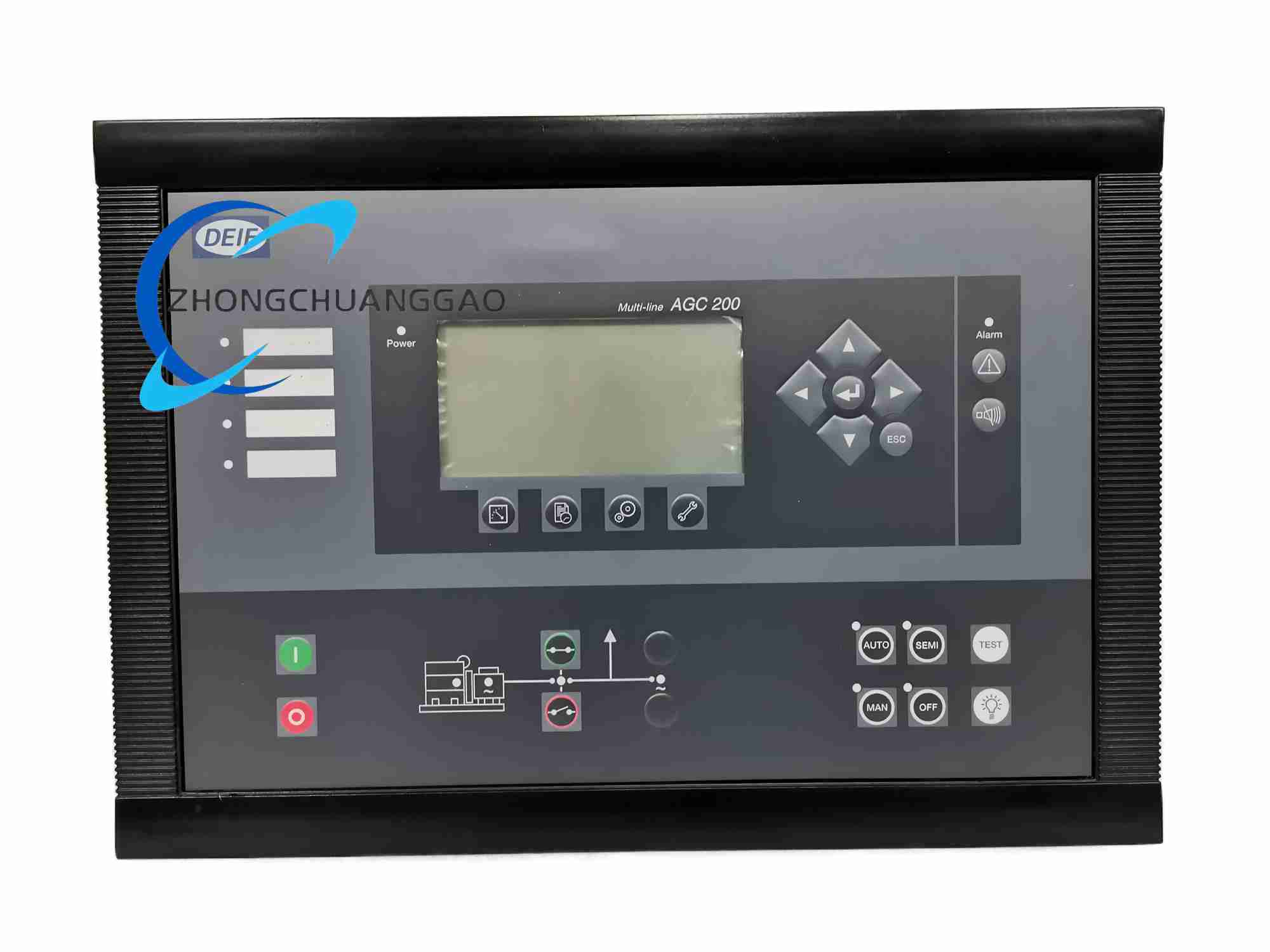
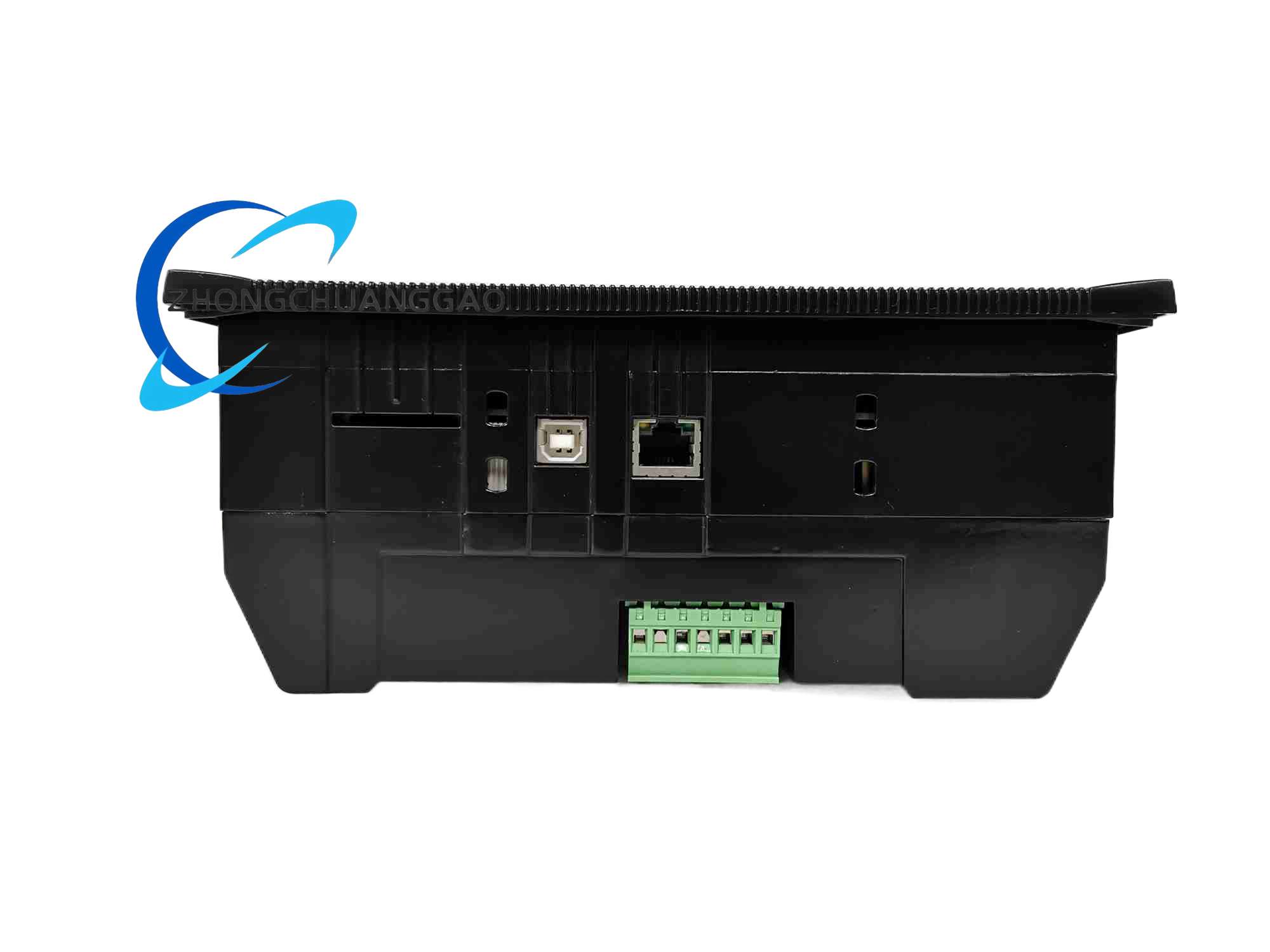
Panel-mount genset controller with graphical HMI. Separate electrical measurement inputs, engine sensor inputs and communication ports. Programmable relay and digital I/O section.
Working Principle
The controller measures generator voltage, current, frequency and phase, evaluates engine parameters from sensors or J1939 ECU data, and runs protection, start/stop, synchronizing and load-share algorithms. Outputs control fuel solenoid, starter, breaker and alarm devices.
Installation Requirements
Install in a switchboard panel with adequate ventilation. Provide fused auxiliary DC supply. Connect CTs with correct polarity and PTs with correct phase sequence. Use shielded twisted-pair cable for communication and sensor circuits. Terminate CAN bus with correct resistances.
Usage Precautions
Configure all protection setpoints before paralleling. Verify CT polarity and PT phase sequence. Test synchronization window before live breaker closing. Backup configuration with PC-Tool 200. Inspect alarm and event logs during periodic maintenance.