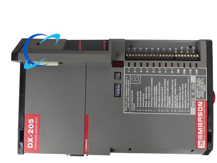
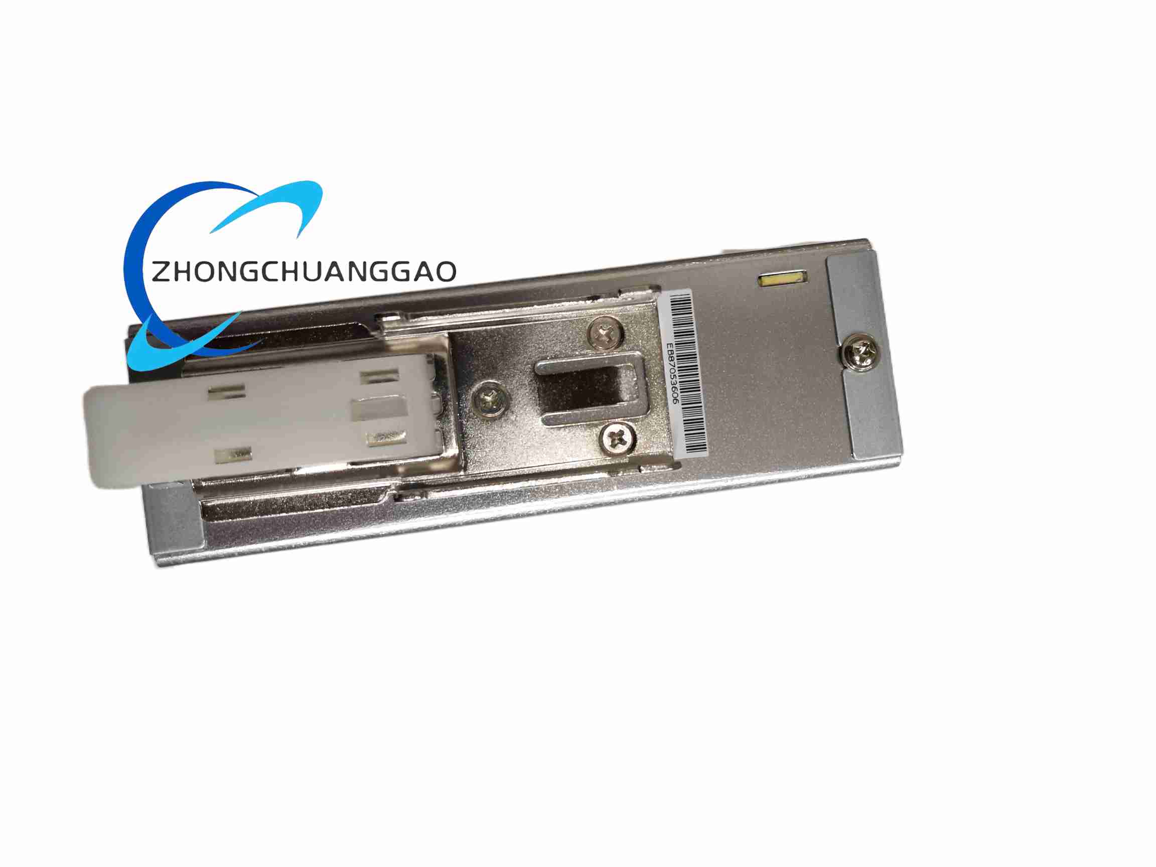
DANAHER AHD70E4-44S
Product Name
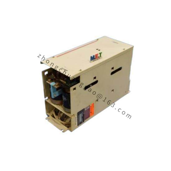
DANAHER AHD70E4-44S servo drive unit
Product Introduction
The AHD70E4-44S is an industrial servo drive. The product description and full technical data sheet were not found in the available public manufacturer documentation. Therefore, the exact ratings, supported motor types, feedback interfaces, and safety functions cannot be confirmed.
Detailed content
Technical Specifications
- Publicly confirmed electrical ratings: not found
- Publicly confirmed output current: not found
- Publicly confirmed control modes: not found
- Publicly confirmed communication interfaces: not found
- Publicly confirmed environmental ratings: not found
Function Features
The general purpose of this equipment family is precision speed, torque, and position control of industrial servo motors. Specific features applicable to the AHD70E4-44S could not be verified from official documentation.
Application Scenarios
- Packaging machinery
- Printing and converting equipment
- Material handling systems
- Robotics and gantry equipment
- Machine tools
- Automated test and assembly systems
Performance Parameters
No verified numerical performance data are available for this exact part number.
Material Composition
- Metal heat-dissipating enclosure
- Printed circuit board
- Power semiconductors
- Control and interface connectors
- Terminal block
- Internal cooling components
Structural Features
- Cabinet-mounted servo amplifier
- Front or local access to terminals and indicators
- Backplane or rack-compatible industrial form factor
- Motor power and feedback connection points
- Control input and output terminals
Working Principle
A servo drive converts incoming AC supply power into controlled voltage and current for the servo motor. It receives command signals from a motion controller, reads motor feedback, and continuously adjusts current, speed, or position to follow the commanded motion profile.
Installation Requirements
- Mount in a ventilated control cabinet
- Maintain manufacturer-specified clearance above and below the drive
- Use copper conductors sized for the expected continuous current
- Provide separate routing for motor power, feedback, and low-voltage control cables
- Bond the enclosure and shield according to the installation manual
- Verify compatibility with the connected motor, feedback device, and control system
Usage Precautions
- Do not operate the drive without confirming motor and load compatibility.
- DC bus and motor terminals can remain energized after power removal.
- Verify that regenerative energy and braking requirements do not exceed drive limits.
- Use personal protective equipment and lockout or tagout procedures during installation.
- Only qualified personnel should perform commissioning and parameter changes.