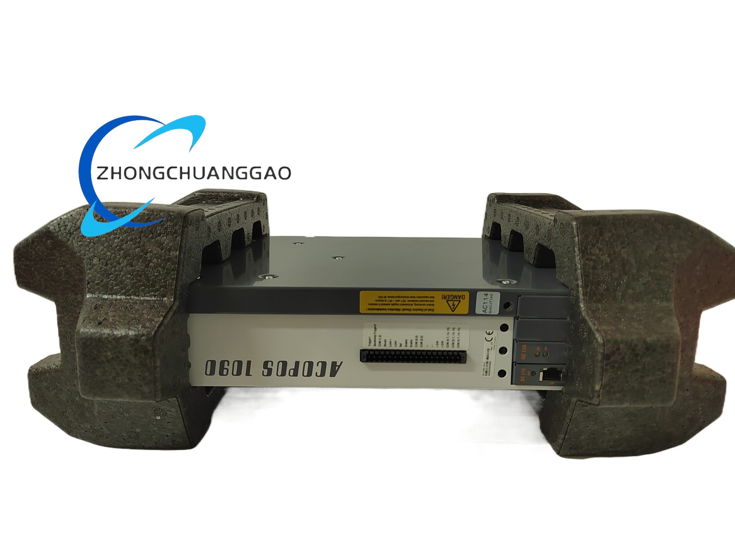
B&R X20TB12
Product Introduction:
The B&R X20TB12 is a 12-point screw-type terminal block designed for the B&R X20 I/O system. It provides a clean, organized connection point for field wiring to X20 I/O modules. The module features 12 individual screw terminals rated for 16 A / 250 V, enabling reliable connection of sensors, actuators, and other field devices.
Detailed content
Technical Specifications:
- Number of Terminals: 12
- Rated Current per Terminal: 16 A
- Rated Voltage: 250 V AC / DC
- Wire Cross Section: 0.5 mm² to 2.5 mm² (solid), 0.5 mm² to 4 mm² (stranded with ferrule)
- Screw Torque: 0.8 Nm (recommended)
- Wire Stripping Length: 10 mm
- Isolation Voltage: 500 V DC (between terminals)
- Pollution Degree: 2 (per IEC 60664)
- Operating Temperature: 0°C to +55°C
- Storage Temperature: -25°C to +70°C
- Dimensions (W x H x D): 44 mm x 90 mm x 115 mm
- Weight: Approx. 0.12 kg
- Mounting: DIN rail TS 35 (EN 60715)
Functional Features:
- 12 individual screw-clamp terminals for field wiring
- Clear terminal numbering for easy identification
- Color-coded terminal marks (white label with black numbering)
- DIN rail clip for secure mounting
- Tool-free connection via standard screwdriver (1.5 mm slot)
- Pre-wired bridge connections available for common signal grouping
Performance Parameters:
- Contact Resistance: < 3 mΩ (initial)
- Contact Resistance (after life test): < 5 mΩ
- Mechanical Life: > 100 operations (screw/unscrew cycles)
- Electrical Life: > 10,000 operations (at rated load)
- Vibration Resistance: 5 g (per IEC 60068-2-6)
- Shock Resistance: 15 g (per IEC 60068-2-27)
Material Composition:
- Housing: Flame-retardant PA66 (polyamide 6.6) with glass fiber reinforcement, UL 94 V-0 rated
- Terminal Screws: Zinc-plated steel, corrosion-resistant
- Terminal Contacts: Tin-plated copper alloy (CuSn6) for reliable conductivity
- Label Strip: Polycarbonate (PC), UV-resistant, printable
- DIN Rail Clip: Spring steel, tin-plated
Structural Features:
- Standard X20 module width: 44 mm
- Front-facing bus connector for X20 system connection
- Screw terminals arranged in a single row on the front face
- Label strip on top for terminal identification
- Snap-in DIN rail mounting with locking mechanism
Working Principle:
The X20TB12 serves as a passive wiring distribution point. Field devices are connected to the screw terminals, and the electrical signals are routed through the terminal block to the corresponding X20 I/O module via the X20 bus connector on the rear of the module. There is no active electronics in this module; it purely provides a mechanical and electrical interface between field wiring and the X20 system. The screw-clamp mechanism ensures a gas-tight connection that resists vibration and thermal cycling.
Advantages & Highlights:
- Simple, reliable passive connection with no electronics to fail
- 16 A rated current handles most standard field device loads
- Clear labeling reduces wiring errors during installation and maintenance
- DIN rail mounting integrates seamlessly with X20 system
- Wide wire acceptance range (0.5–4 mm²) accommodates various cable types
- UL 94 V-0 flame-retardant housing for safety compliance
Applicable Industries:
- Machine building (general purpose)
- Packaging machinery
- Conveyor systems
- Material handling equipment
- Textile machinery
- Woodworking machines
Installation Requirements:
- Mount on DIN rail TS 35 (EN 60715)
- Connect to X20 bus via rear-facing bus connector
- Use wire ferrules for stranded conductors (≥ 0.5 mm²)
- Strip wire to exactly 10 mm for optimal connection
- Torque screws to 0.8 Nm using 1.5 mm flathead screwdriver
- Group signals logically on the terminal block (e.g., all 24 V on one side, all signals on the other)
Usage Precautions:
- Do not exceed 16 A per terminal under any condition
- Do not mix solid and stranded wires on the same terminal
- Always use wire ferrules for stranded conductors to prevent fraying
- Do not overtighten screws (max 0.8 Nm) to avoid damaging terminal threads
- Verify all connections before applying power to the system
- Do not use in environments exceeding +55°C ambient temperature