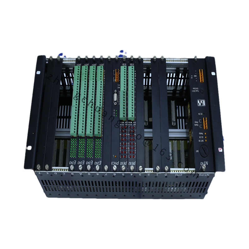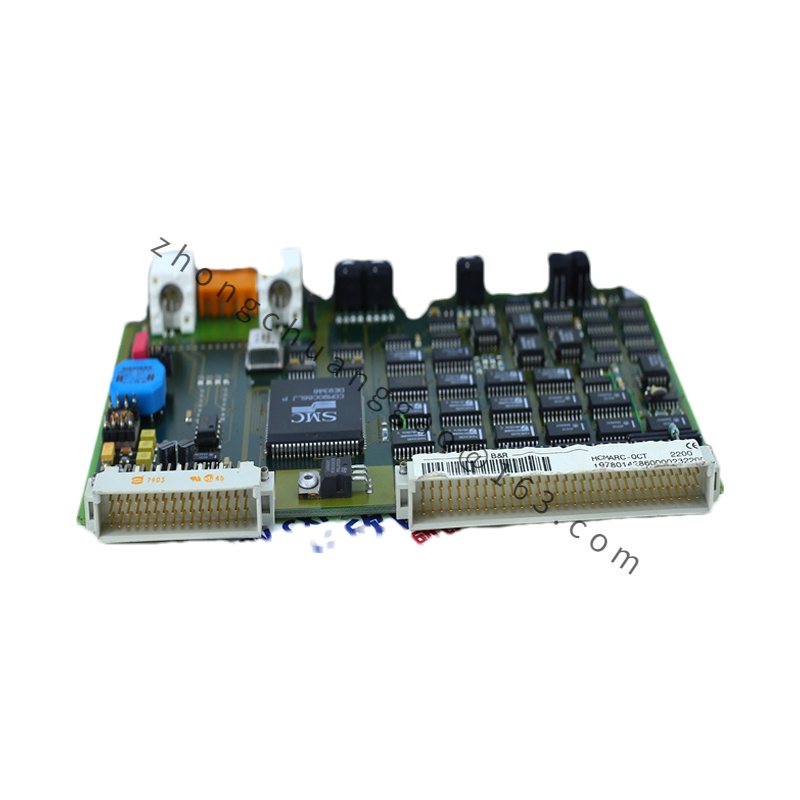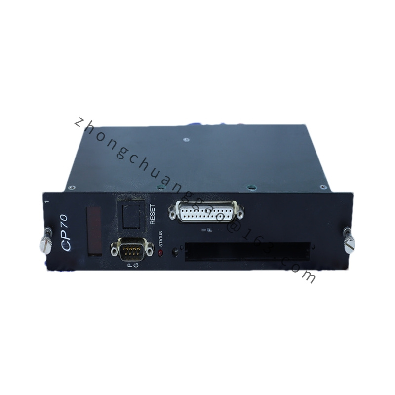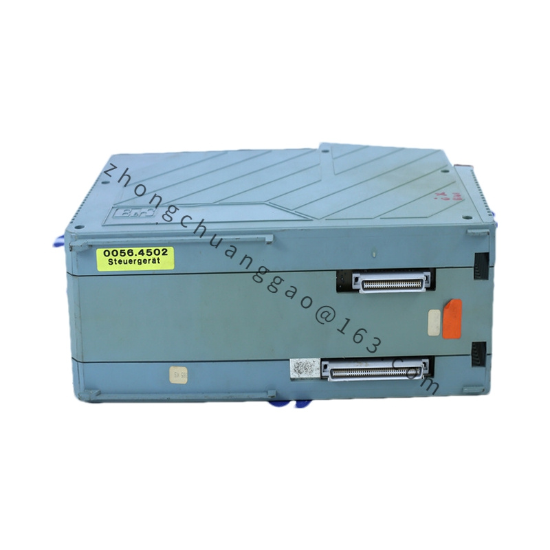
B&R X20SO6300
Product Introduction:
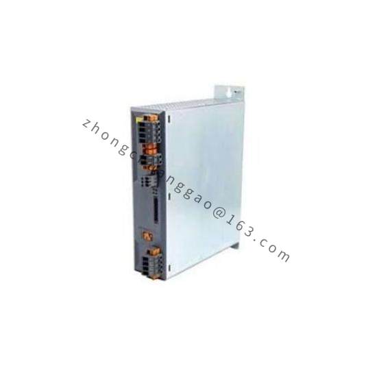
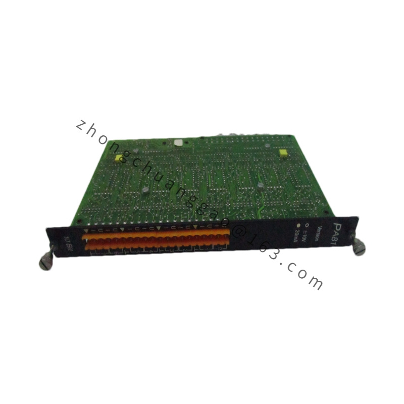
The B&R X20SO6300 is a 6-channel analog output module from the B&R X20 system. It delivers precision current outputs in the range of 0–20 mA or 4–20 mA with 16-bit resolution. Each channel is individually configurable and electrically isolated, making it ideal for process control applications requiring accurate analog signal generation.
Detailed content
Technical Specifications:
- Number of Channels: 6
- Output Type: Current (0–20 mA / 4–20 mA)
- Resolution: 16 bit (65,536 steps)
- Accuracy: ±0.1% of Full Scale (FS)
- Linearity Error: ±0.05% FS
- Update Rate: 1 ms (all channels simultaneously)
- Isolation: Channel-to-channel galvanic isolation
- Isolation Voltage: 500 V DC (channel to channel, channel to bus)
- Output Load: 0 to 600 Ω (at 24 V DC supply)
- Supply Voltage (Bus): 24 V DC (from X20 bus)
- Operating Temperature: 0°C to +55°C
- Storage Temperature: -25°C to +70°C
- Dimensions (W x H x D): 44 mm x 90 mm x 115 mm
- Weight: Approx. 0.2 kg
Functional Features:
- 6 independently configurable current output channels
- Selectable output range: 0–20 mA or 4–20 mA per channel
- 16-bit D/A converter per channel for high precision
- Channel-to-channel isolation prevents ground loop issues
- Diagnostic capabilities: Wire break detection, short-circuit detection, overload detection
- LED status indicators per channel for operation and fault status
- Software-configurable via B&R Automation Studio
- Scaling and offset adjustable per channel in software
Performance Parameters:
- Output Current Accuracy: ±0.1% FS (at 25°C)
- Temperature Drift: ±10 ppm/°C
- Settling Time: < 10 µs (to 0.01% of final value)
- Common Mode Rejection Ratio (CMRR): > 120 dB
- Power Consumption (Bus): < 1.5 W
Material Composition:
- Housing: Flame-retardant PA66 (polyamide 6.6) with glass fiber reinforcement
- Terminals: Tin-plated copper alloy with spring-cage or screw clamp connection
- PCB: FR-4 glass fiber epoxy laminate, conformally coated
- Isolation Barrier: Reinforced insulation with >500 V rating
Structural Features:
- DIN rail mountable (TS 35, EN 60715)
- Front-facing X20 bus connector
- Screw-terminal output connections (2-wire or 4-wire configuration selectable)
- LED indicators on front panel: Channel status, Fault, Bus communication
- Modular width: 44 mm (standard X20 module width)
Working Principle:
The X20SO6300 receives digital values from the controller via the X20 bus. Each of the 6 channels contains an independent 16-bit D/A converter that transforms the digital input value into a proportional analog current signal. The output stage uses a precision current source circuit with feedback control to maintain accuracy across the full load range. Channel-to-channel galvanic isolation is achieved through optical or magnetic isolation barriers, ensuring that faults or noise on one channel do not affect other channels. The module supports both 2-wire (loop-powered) and 4-wire (externally powered) connections.
Advantages & Highlights:
- High precision 16-bit resolution for demanding process control
- True channel isolation eliminates cross-talk and ground loop problems
- Fast 1 ms update rate for dynamic control applications
- Wide load range (0–600 Ω) provides flexible field wiring options
- Comprehensive diagnostics reduce downtime and maintenance costs
- Software-configurable eliminates need for hardware jumper settings
Applicable Industries:
- Process automation (chemical, pharmaceutical)
- HVAC control systems
- Flow and pressure control
- Valve positioning systems
- Batch processing
- Water and wastewater treatment
Installation Requirements:
- Mount on DIN rail TS 35 (EN 60715)
- Connect to X20 system bus via front-facing connector
- Use shielded twisted-pair cables for analog outputs in noise-sensitive environments
- For 4–20 mA operation, ensure loop supply voltage ≥ 24 V DC
- Ground the shield at one end only to avoid ground loops
- Torque terminal screws to 0.8 Nm
Usage Precautions:
- Do not exceed 600 Ω total loop resistance per channel
- Do not apply voltage directly to current output terminals (current source)
- Verify output range configuration in software before commissioning
- Ensure proper bus power supply (24 V DC, min. 5 A recommended for full system)
- Do not disconnect output loads while the module is energized (may cause voltage spikes)
- Use shielded cables in electrically noisy environments