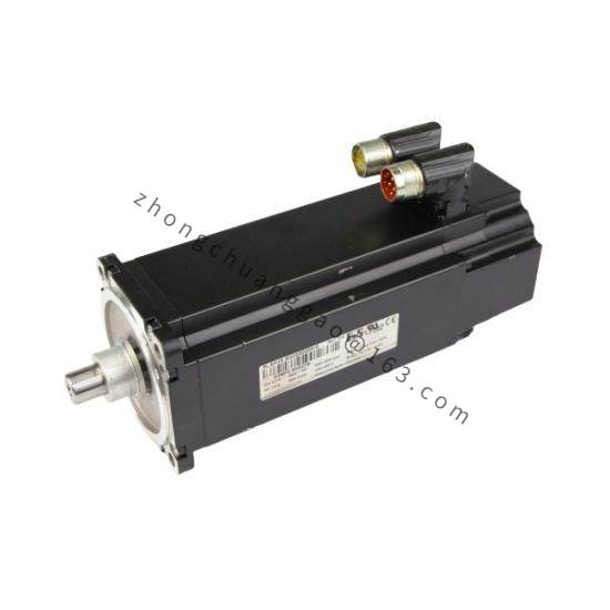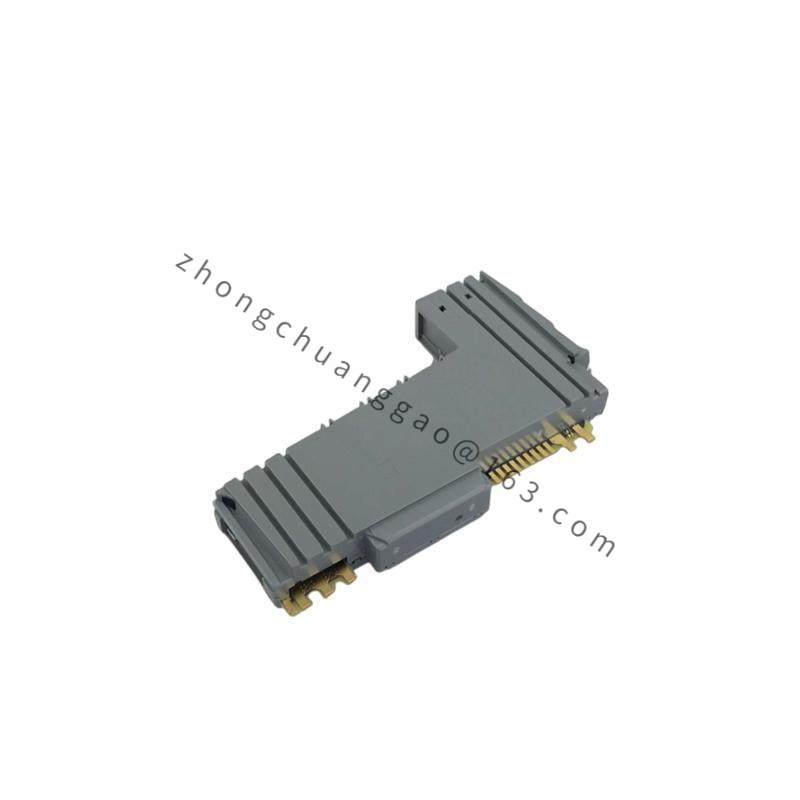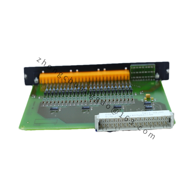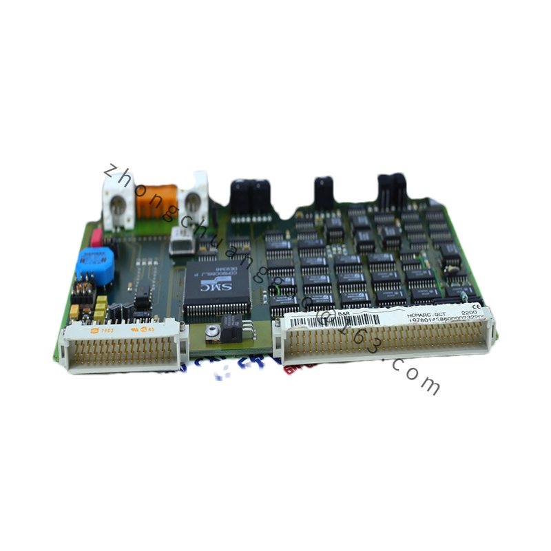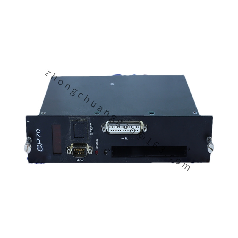
B&R X20DC2398
Product Series: B&R X20 Series (Compact I/O System)
Product Introduction:
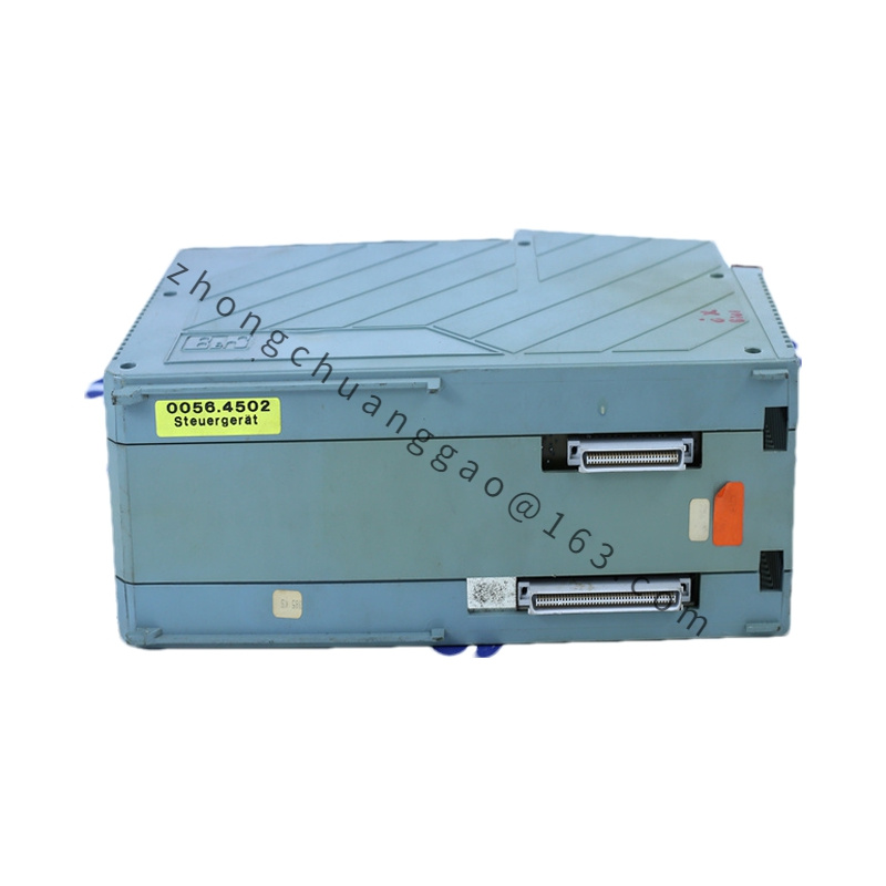
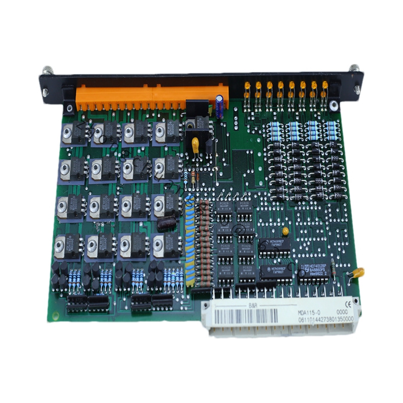
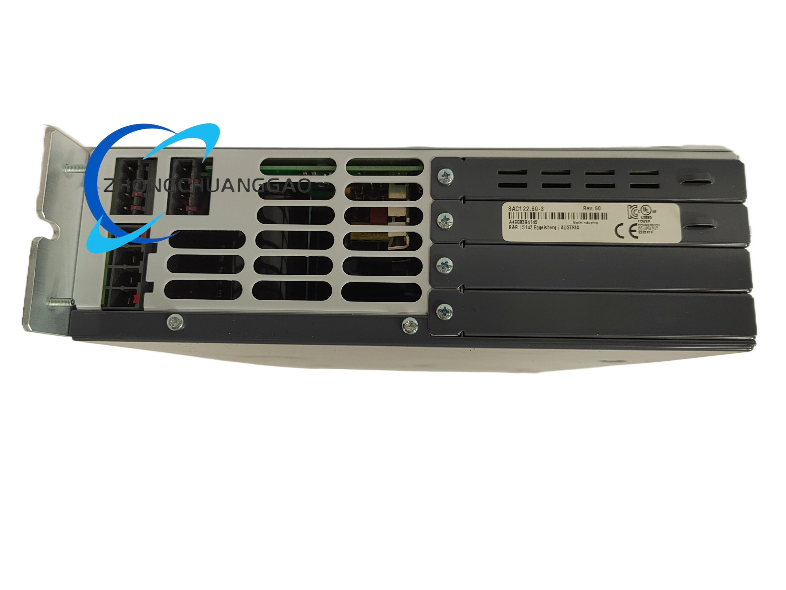
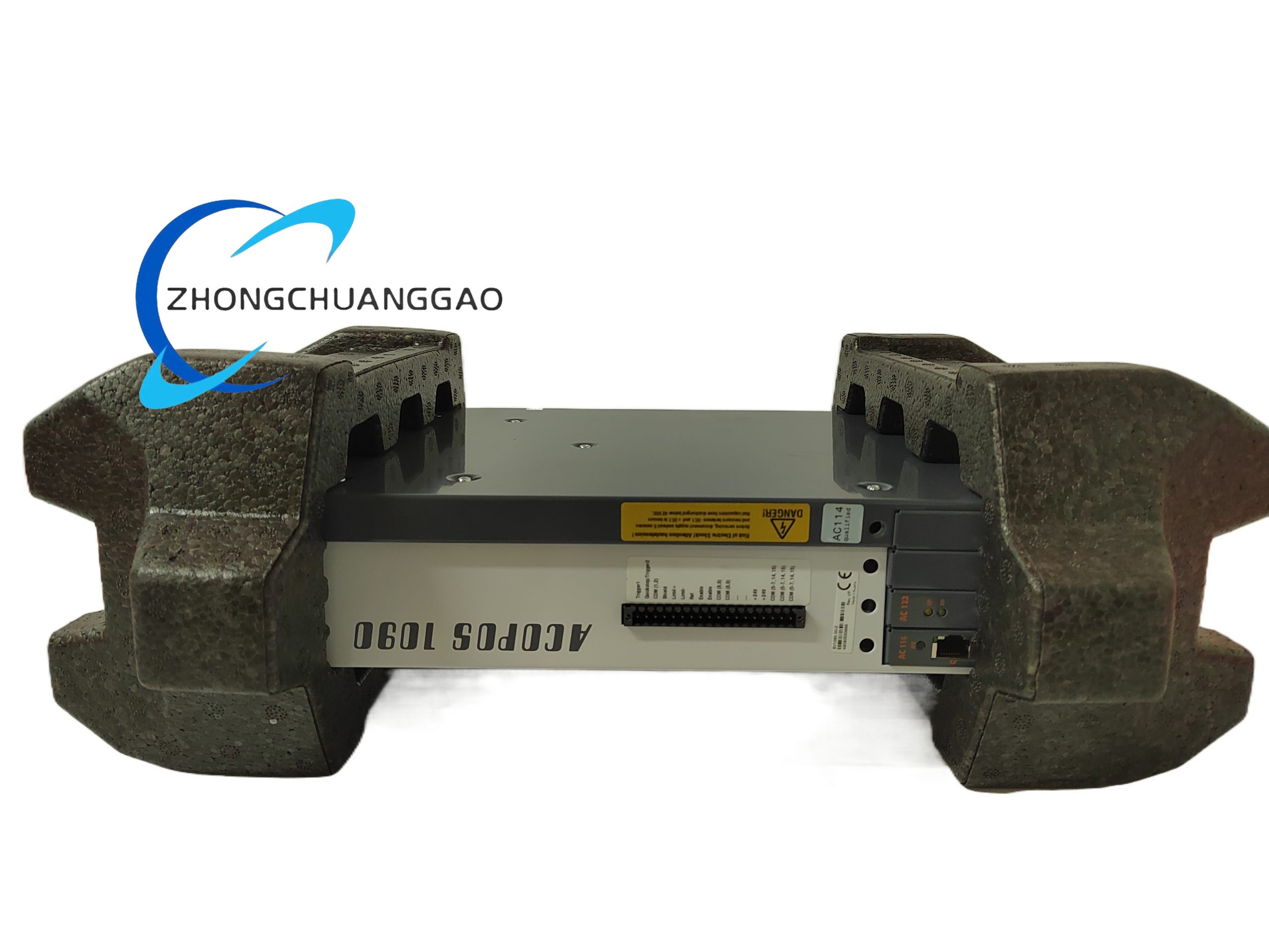
The B&R X20DC2398 is a 8-channel digital output module from the B&R X20 compact I/O system. It provides 8 sink-type digital output channels operating at 24 VDC with a maximum current rating of 0.5 A per channel. This module is designed for direct field device control in industrial automation environments and integrates seamlessly into the B&R X20 backbone system via the M12 connector interface.
Detailed content
Technical Specifications:
| Parameter | Value |
|---|---|
| Number of Channels | 8 digital outputs |
| Output Type | Sink (NPN) |
| Output Voltage | 24 VDC |
| Output Current per Channel | 0.5 A |
| Total Output Current | 4 A (aggregate) |
| Logic Level “1” | 24 VDC (active HIGH) |
| Logic Level “0” | 0 V (GND, active LOW) |
| Switching Frequency | Up to 10 kHz |
| Response Time (ON→OFF / OFF→ON) | ≤ 1 ms |
| Isolation Voltage | 500 V DC (channel to channel, channel to backplane) |
| Protection Class | IP20 (front side), IP67 (when mated with M12 connector) |
| Connector Type | M12, 8-pin, A-coded |
| Supply Voltage | 24 VDC via backplane bus |
| Power Consumption (max) | ~2.5 W |
| Operating Temperature | -25 °C to +70 °C |
| Storage Temperature | -40 °C to +85 °C |
| Relative Humidity | 5 % to 95 % (non-condensing) |
| Dimensions (W × H × D) | 25 mm × 90 mm × 75 mm |
| Weight | ~85 g |
| Certifications | CE, UL, CSA, ATEX (Zone 2) |
Functional Features:
- 8 independent sink-type digital outputs for controlling solenoid valves, relays, indicator lamps, and contactor coils
- Short-circuit protection on each individual channel
- Overcurrent protection with automatic shutdown per channel
- Overtemperature protection with thermal shutdown
- LED status indicators per channel for real-time diagnostics (green = active, red = fault)
- Galvanic isolation between channels and backplane for noise immunity
- Diagnostic feedback via backplane to the controller (CPU)
Structural Features:
- Compact plastic housing made from polycarbonate (PC) + glass fiber reinforced (GF)
- M12 connector on the front for field wiring
- Backplane connector on the bottom for mounting into the X20 base or X20HB terminal base
- DIN rail mountable (35 mm top-hat rail, TS 35)
- Screw-type terminal connections on M12 connector
Working Principle:
The module receives digital commands from the B&R controller (e.g., X20CP1484, X20CP0484) via the backplane bus. Each of the 8 output channels contains an NPN power transistor (sink configuration). When the controller sets a channel to logic “1”, the corresponding transistor switches ON, connecting the output terminal to GND (0 V), thereby allowing current to flow from the external 24 VDC load through the load and into the output terminal (sink current). When logic “0” is set, the transistor switches OFF, opening the circuit.
Advantages & Highlights:
- Ultra-compact design — saves up to 50 % cabinet space compared to conventional I/O modules
- M12 connector technology — enables fast, tool-free wiring and high IP67 protection at the field side
- Per-channel diagnostics — immediate fault identification without external measurement
- Sink configuration — ideal for European standard field devices (PNP sensors with external pull-up)
- High switching speed up to 10 kHz — suitable for fast cycling applications
Applicable Industries:
- Packaging machinery
- Material handling & conveyor systems
- Assembly line automation
- Plastics processing machinery
- Textile machines
- Food & beverage production lines
- Printing machines
Installation Requirements:
- Mount on 35 mm DIN rail (EN 60715)
- Ensure minimum 10 mm clearance above and below the module for ventilation
- Use M12 8-pin A-coded cables for field-side connections (max cable length: 100 m depending on cable type)
- Tighten M12 connector to torque of 1.5 Nm
- Connect 24 VDC power exclusively via the X20 backplane bus — do NOT apply external power to output terminals
Usage Precautions:
- Do not exceed 0.5 A per channel — overcurrent will trigger protection and may damage the module
- Do not apply voltage > 30 VDC to any output terminal
- Do not mix sink and source outputs on the same load without proper interface circuit
- Ensure proper grounding of the 24 VDC power supply
- Do not disconnect M12 connector under load — always power down before disconnecting
- Observe ATEX zone requirements when used in explosive atmospheres (Zone 2 certified)