Detection Type
Ultraviolet flame detection
Detection band: 180 to 260 nm
Supply Voltage
Common listed versions: 24 VDC, 28 VDC, or 115 VAC
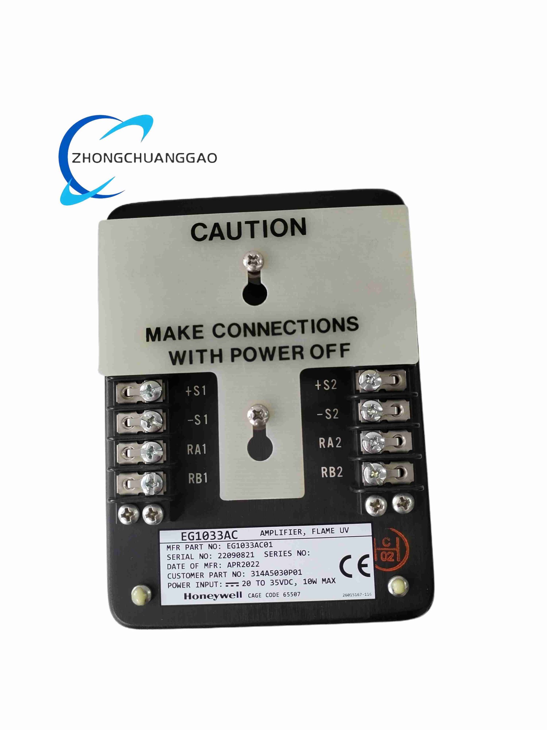
Nameplate examples also list 20 to 35 VDC, 10 W max
Exact supply depends on ordered version
Output
0 to 10 VDC analog version
SPDT relay version: 5 A at 250 VAC or 30 VDC
Version must be confirmed from nameplate
Gain
100 to 1000 times adjustable
Frequency Response
20 Hz to 20 kHz
Response Time
Flame established: 0.1 s or less
Flame lost: 0.2 s or less
Operating Temperature
Common listing: -40 to 85 °C
Some versions list -40 to 75 °C or higher intermittent ratings
Storage Temperature
-55 to 125 °C
Humidity
0 to 95%, non-condensing
Enclosure
Industrial encapsulated electronics
Metal or industrial plastic housing depending on version
UV-resistant lens
IP65 listed for some versions
Certifications
CE
TÜV
UL
CSA
ATEX or FM listed for some combustion applications
Application Scenarios
Boilers
Gas turbines
Industrial furnaces
Petrochemical heaters
Glass furnaces
Refinery burners
Power plant burners
Incineration systems
Working Principle
Flame UV photons strike the Geiger-Müller tube and create pulses. The amplifier counts and conditions the pulses, compares the result with the threshold, and drives the analog or relay output to indicate flame on or flame lost.
Installation Requirements
Mount in the specified control cabinet, panel, or DIN-rail arrangement.
Orient the UV sensor or probe toward the flame observation zone.
Use shielded cable for UV detector and amplifier wiring.
Ground the shield correctly.
Confirm hazardous-area certification before installation in explosive atmospheres.
Usage Notes
Do not expose the UV tube to direct sunlight or welding arcs during setup.
Periodically test with a certified UV source.
Balance gain to avoid false trips while maintaining sensitivity.
Replace the UV tube at end of life according to the manual.
Never bypass flame-loss interlock during operation.