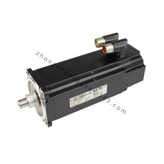

Model Series: X20 Bus System — Service & Diagnostic Tools
Product Overview:
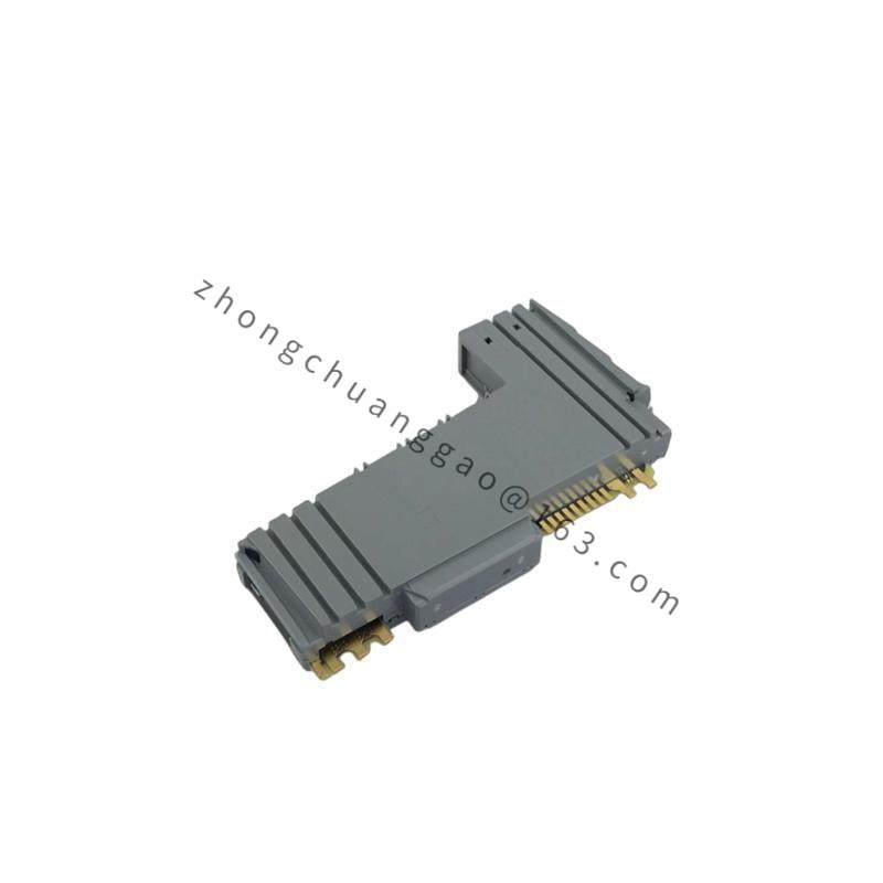
The B&R 8SCS005.0000-0 is a Service Coupler for the B&R X20 distributed I/O system. It provides a dedicated interface for commissioning, diagnostics, parameterization, and firmware updates of all X20 modules without removing them from the bus. It connects between the X20 bus coupler and the first I/O module in the chain.
Technical Specifications:
| Parameter | Value |
|---|---|
| Interface | X20 bus connector (top and bottom) |
| Communication | X20 bus protocol (500 µs cycle time) |
| Connection to PC | USB 2.0 (Mini-B connector) |
| LED Indicators | Power, Bus activity, Error |
| Operating Temperature | 0 °C to +55 °C |
| Storage Temperature | -25 °C to +70 °C |
| Dimensions (W x H x D) | 25 mm x 90 mm x 74.5 mm |
| Weight | Approx. 80 g |
| Mounting | DIN rail TS 35 (EN 60715) |
| Certifications | CE, UL |
Functional Features:
Applicable Industries:
All industries using B&R X20 systems — commissioning, maintenance, and troubleshooting.
Installation Requirements:
Product Name: B&R X20 TB31 — Bus Terminal Module with LED Indicators
Model Series: X20 Bus System — Bus Termination
Product Overview:
The B&R 8V1320.00-2 is a bus terminal module for the B&R X20 distributed I/O system. It is installed at the last position of the X20 bus segment to provide proper electrical termination of the bus line, preventing signal reflections. It features integrated LED status indicators for visual bus health monitoring.
Technical Specifications:
| Parameter | Value |
|---|---|
| Function | Bus termination with LED status |
| Termination Resistance | 120 Ω (integrated) |
| LED Indicators | Power (green), Bus activity (yellow), Error (red) |
| Bus Cycle Time | 500 µs |
| Power Consumption from Bus | ≤ 0.5 W |
| Operating Temperature | 0 °C to +55 °C |
| Storage Temperature | -25 °C to +70 °C |
| Dimensions (W x H x D) | 25 mm x 90 mm x 74.5 mm |
| Weight | Approx. 70 g |
| Mounting | DIN rail TS 35 (EN 60715) |
| Certifications | CE, UL, cUL, ATEX (Zone 2) |
Functional Features:
Applicable Industries:
All B&R X20 system installations across every automation sector.
Installation Requirements: