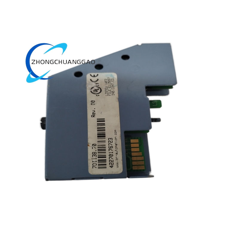
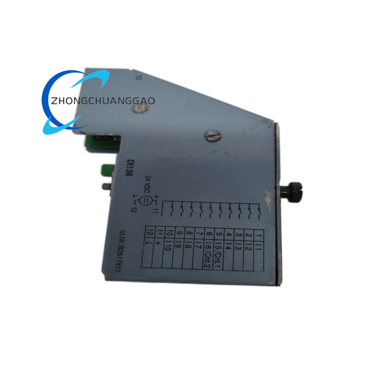
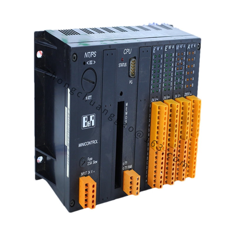
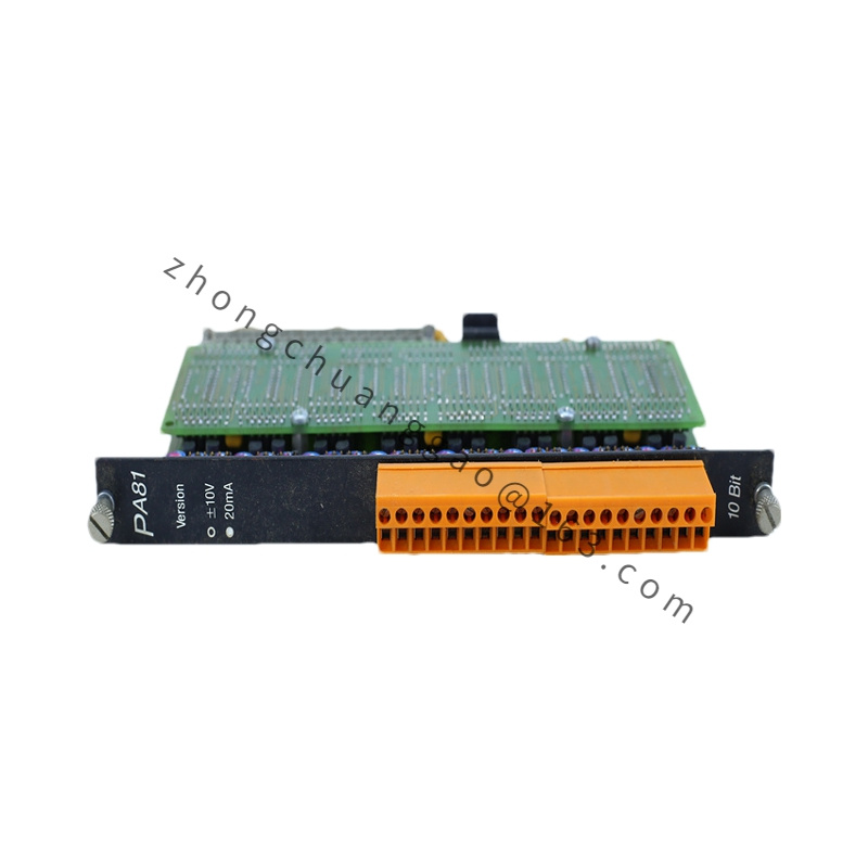
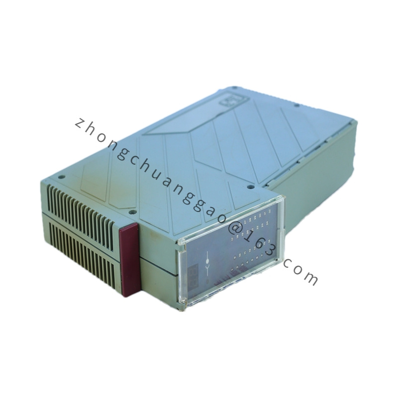
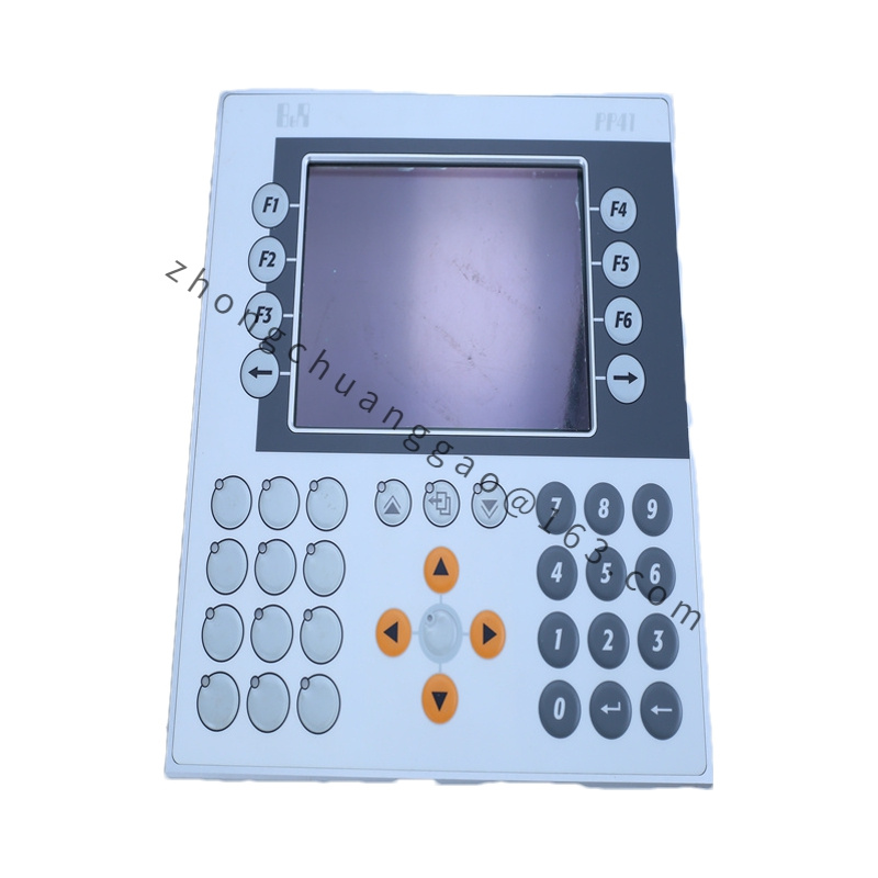
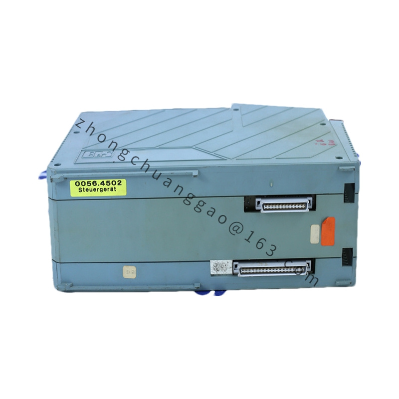
Technical Specifications: Ten digital inputs, 24 VDC sink, IEC 1131 Type 1. Input voltage range 18 VDC to 30 VDC, nominal 24 VDC. Switching threshold 15 V. Inputs 5 and 6 support event counters; counter input frequency 20 kHz, count frequency 40 kHz, 16-bit counter size. Other inputs standard filtering. Input current inputs 5 and 6 approximately 8 mA at 24 VDC; other inputs approximately 5 mA at 24 VDC. Input delay inputs 5 and 6 maximum 3 µs; other inputs maximum 1.3 ms. Electrical isolation between inputs and PLC. Maximum power consumption 0.4 W. Required terminal block 7TB712.9 screw clamp or 7TB712.91 cage clamp, ordered separately. Twelve-pin assignment: inputs 1 to 10, pin 11 +24 VDC supply, pin 12 GND.
Function Features: Two high-speed counter channels with 16-bit resolution. Supply voltage monitoring. IEC 1131 Type 1 sink input design. Compatible with AF101 adapter and System 2003 screw-in I/O mapping.
Application Scenarios: Discrete signal acquisition for System 2003 PLCs. Pulse counting from encoders, flow meters and high-speed sensors. Power Panel digital expansion where screw-in modules are used.
Performance Parameters: Counter input frequency 20 kHz. Count evaluation frequency 40 kHz. High-speed input response below 3 µs. Standard input response below 1.3 ms. Isolation between field inputs and controller backplane.
Material Composition: System 2003 screw-in module body. Optocoupler isolation components. Spring or screw terminal interface through separate TB712 terminal block. PCB with sink-input filtering and counter logic.
Structure Characteristics: Compact screw-in module for CP interface or AF101 adapter. Twelve-pin terminal block separate from module. No onboard status LEDs. Logical system mapping treats the module data as analog-style data words in certain System 2003 configurations.
Working Principle: Each sink input pulls the field signal to ground through current-limiting and filtering stages. Optocouplers transfer the logic state to the PLC backplane. Counter channels decode square-wave pulses on inputs 5 and 6, accumulate counts in 16-bit registers and report values through system data words.
Installation Requirements: Install in a compatible System 2003 slot, CP interface or AF101 adapter. Fit the separately ordered 7TB712 terminal block before wiring. Connect field inputs to pins 1 to 10, supply +24 VDC to pin 11 and GND to pin 12. Verify sink wiring for sensors and switches.
Usage Precautions: Terminal block is not included and must be ordered separately. Use a clean, stabilized 24 VDC supply because high-speed inputs are sensitive to voltage transients. Install varistor or suppression components in the supply line when the environment has inductive loads. Confirm counter configuration in the PLC before relying on high-speed counting. Do not exceed 30 VDC input or 0.4 W module power.