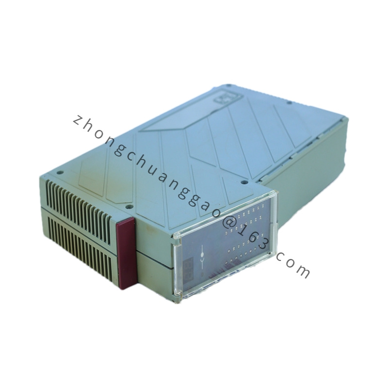
Technical Specifications
System family: B&R Automation PC 810
Example material: 5PC810.SX05-00
Processor: depends on installed APC810 CPU board
Graphics: depends on CPU board
Real-time clock: battery-backed
Power-failure buffer: controller MTCX, 10 ms buffer time
SRAM: 512 kB battery-backed; remanent variables 192 kB according to runtime configuration
Storage: 2 x CompactFlash Type I, 2 slide-in drive positions, 1 slide-in compact position according to build
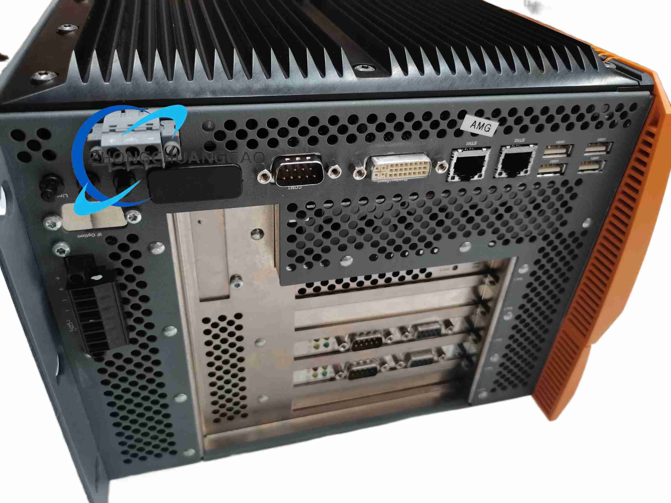
Ethernet: 2 x RJ45, 10/100/1000 Mbit/s, shielded
Serial: 2 x RS232, 9-pin DSUB, 16550-compatible, 16-byte FIFO, up to 115 kbit/s
USB: 5 x USB 2.0 Type A; low speed 1.5 Mbit/s, full speed 12 Mbit/s, high speed 480 Mbit/s; 500 mA or 1 A per port according to connector build
Display: DVI-I female for DVI, VGA adapter or Smart Display Link
Audio: AC97 microphone, line-in, line-out
Expansion slots: 4 PCI and 1 PCIe, or 2 PCI and 3 PCIe, or 5 PCI according to bus unit
Additional slots: 1 add-on interface slot, Automation Panel Link slot, add-on UPS slot, fan-kit slot
CAN: optional according to CPU board
Battery: Renata 950 mAh lithium-ion, removable, front service door; SX05-00 service life approximately 2.5 years, other builds approximately 4 years according to battery pack
Power: 24 VDC ±25%, SELV
Nominal current: 6 A for high-slot system units such as SX05-00; verify suffix-specific current for two-slot builds
Inrush current: typical 7 A, maximum 50 A for less than 300 µs on SX05-00
Protection: IP20
Certifications: CE, UKCA, UL cULus E115267, KC according to regional variant
Functional Features
Configurable PCI and PCIe expansion for fieldbus, motion, vision and I/O cards
Gigabit Ethernet for programming, HMI, SCADA and controller synchronization
Automation Panel Link for long-distance B&R operator panels
Dual CompactFlash and slide-in drives for redundant or separated system and data storage
Battery-backed SRAM and real-time clock for retentive automation data
Application Scenarios
Large machine-control systems with multiple communication networks
Multi-axis motion and CNC support computers
Central HMI and SCADA servers in manufacturing cells
High-expansion retrofit projects requiring PCI or PCIe industrial cards
Performance Parameters
Ethernet: 10/100/1000 Mbit/s per port
Serial: RS232 up to 115 kbit/s per port
USB: USB 2.0 up to 480 Mbit/s
SRAM retain: 512 kB; application remanent memory depends on runtime and CPU board
Power-loss buffer: 10 ms through controller MTCX logic
Vibration continuous operation: 2 to 9 Hz at 1.75 mm amplitude, 9 to 200 Hz at 0.5 g
Shock operation: 15 g, 11 ms
Operating elevation: up to 3000 m component-dependent
Material Composition
Housing: galvanized plate with plastic components
Front cover: dyed orange plastic similar to Pantone 144CV
Coating: light gray similar to Pantone 427CV, dark gray similar to Pantone 432CV
Internal assembly: APC810 CPU board, DDR memory, CompactFlash sockets, PCI/PCIe backplane, battery holder
Structural Characteristics
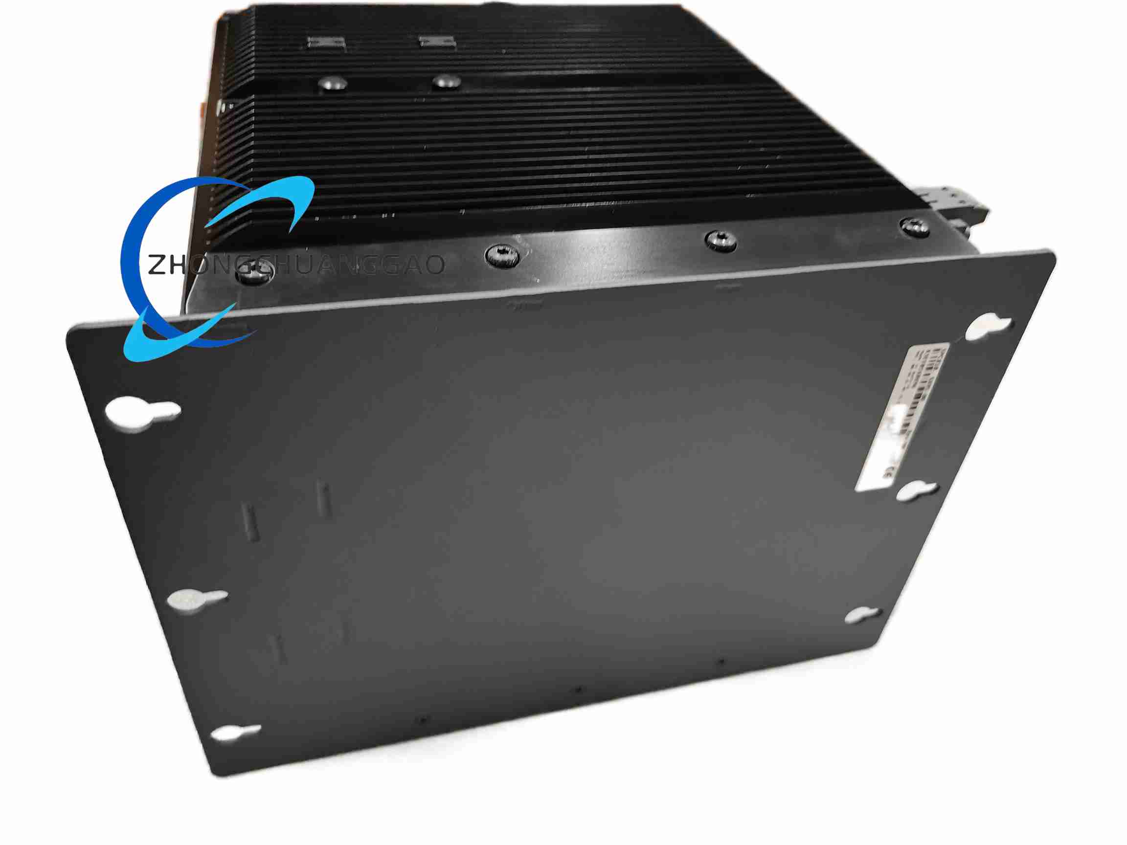
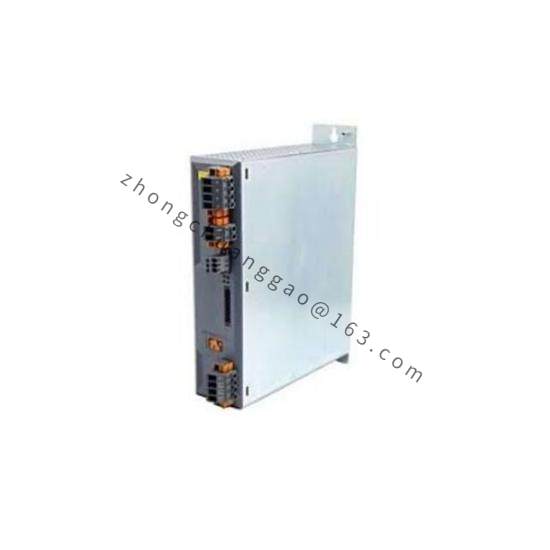
Box system unit for control-cabinet installation
Multiple PCI/PCIe slots with passive or active cooling options
Front service door for battery, power, reset, USB dongle and diagnostics
DVI-I and SDL ready display output
Separate COM, USB, Ethernet, audio and PS/2 interfaces according to CPU board
Working Principle
The APC810 CPU board executes the B&R runtime, Windows embedded image or configured operating system. Gigabit Ethernet ports manage programming, HMI and network communication. PCI or PCIe slots host fieldbus masters, I/O interfaces, motion cards and custom expansion. CompactFlash or slide-in disks store the OS and project. On power interruption, the MTCX logic and battery-backed SRAM retain variables for controlled shutdown or restart.
Installation Requirements
Identify the exact 5PC810 suffix, CPU board, RAM, storage, heatsink and slot configuration before installation.
Provide 24 VDC ±25% SELV power sized for the installed slot load; high-expansion units require up to 6 A nominal.
Mount the chassis in an IP20 cabinet with cooling capacity for the selected processor and cards.
Install the correct Automation Studio firmware, CPU bootloader and driver set.
Use B&R terminal blocks, CompactFlash cards, SDL cables and certified fieldbus modules.
Usage Notes
Different 5PC810 suffixes use different slot counts, current ratings and battery service lives; do not substitute blindly.
Check the CPU-board temperature rating because overall operating limits are component-dependent.
Replace the lithium-ion battery according to the specified service life and local disposal rules.
Verify PCI voltage keys and PCIe mechanical compatibility before inserting expansion cards.
Ground and shield fieldbus cables according to the B&R system manual for the installed communication modules.