
Digital guide

You are here:

B&R 3IP151.60-2

Product Type: 2-Channel High-Speed Counter / Encoder Interface Module

Product Description:
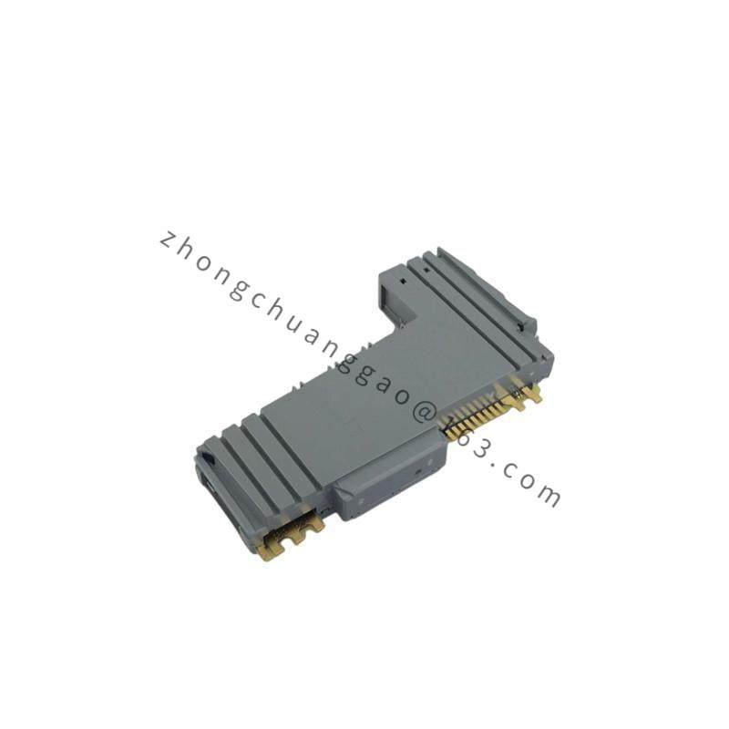
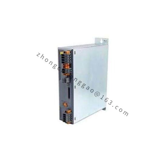
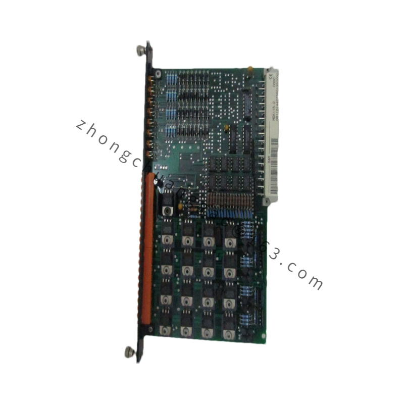
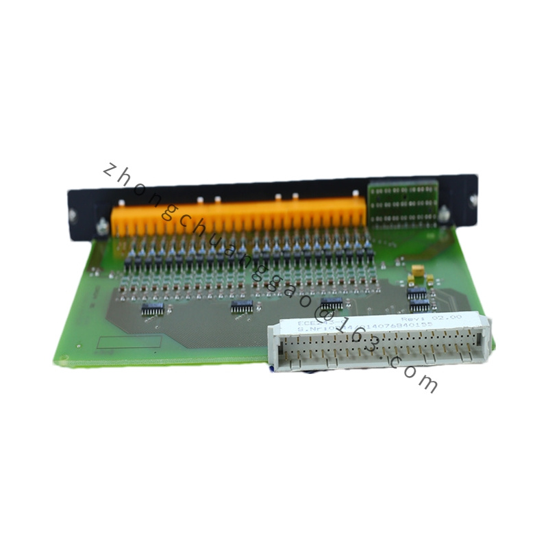
The B&R 3IP151.60-2 is a 2-channel high-speed counter module from the B&R X20 system. It accepts incremental encoder signals (A/B/Z phase) and pulse inputs for precision position counting, speed measurement, and frequency measurement up to 100 kHz. It is essential for servo motor feedback and conveyor position tracking.

Detailed content

Technical Specifications:

  • Number of Channels2 independent counter inputs
  • Counter ModeIncremental encoder (A/B quadrature), single-pulse (A only), up/down counter
  • Maximum Counting Frequency: 100 kHz (500 kHz with quadrature decoding, i.e., 4× counting)
  • Resolution32-bit signed counter (range: -2,147,483,648 to +2,147,483,647)
  • Input Signal Levels: 5 V DC TTL / 24 V DC (configurable per channel)
  • Input Impedance (5 V mode)≥ 100 kΩ
  • Input Impedance (24 V mode)≥ 10 kΩ
  • Filter Time: Configurable: 0.5 µs, 1 µs, 2 µs, 4 µs (hardware debounce)
  • Encoder Types SupportedIncremental (A/B/Z), single-ended pulse, differential (RS-422 via external converter)
  • Isolation: Channel-to-channel isolation, 500 V DC; field-side to logic-side isolation, 500 V DC
  • Bus SystemX20 System Bus
  • Power Supply24 V DC via X20 bus connector
  • Power Consumption: ≤ 1 W
  • Operating Temperature: -25 °C to +70 °C
  • Protection Rating: IP20 (with X20 base/coupler)
  • Dimensions (W × H × D): 25 mm × 90 mm × 75 mm
  • Weight: Approximately 100 g

Functional Features:

  • Quadrature decoding (×1, ×2, ×4) configurable per channel
  • Frequency measurement (gating time: 1 ms to 60 s, configurable)
  • Period measurement (for speed calculation)
  • Zero-pulse (Z) capture for reference/homing
  • Gate input for frequency measurement (external gate signal)
  • Compare function: Counter value compare with preset value → digital output trigger
  • Interrupt on count overflow/underflow

Structural Characteristics:

  • PA66-GF30 plastic housing, UL94 V-0
  • Push-in spring terminal connectors for 0.5 mm² to 2.5 mm² wire
  • DIN rail TS 35 mounting
  • LED indicators: Power (green), Channel 0 (green), Channel 1 (green), Fault (red)

Material Composition:

  • Housing: Glass-fiber reinforced polyamide (PA66-GF30)
  • Terminals: Phosphor bronze, tin-plated
  • PCB: FR-4, conformally coated
  • Counter IC: 32-bit hardware counter with quadrature decoder

Applicable Industries:

  • Servo motor position feedback
  • Conveyor length measurement
  • Winding/unwinding machines (tension control)
  • Printing registration (web position)
  • Elevator/lift position tracking

Installation Requirements:

  • Mount on X20 Base (3EX280.60-1) or X20 Coupler (3EX290.60-1)
  • Use shielded twisted-pair cable for encoder signals (A, B, Z)
  • Shield ground at controller end only (single-point grounding)
  • Maximum cable length: 10 m (5 V TTL), 50 m (24 V, with line driver)
  • For differential encoders (RS-422), use external line receiver (e.g., B&R 3IF360.6)

Usage Notes:

  • Do not exceed 100 kHz input frequency — counts will be lost above this limit
  • For noisy environments, set hardware filter time to 2 µs or 4 µs
  • Z-phase must be connected for homing operations — omit only for pure speed measurement
  • Counter value is retained in non-volatile memory on power loss (battery-backed in some configurations)

You may also like