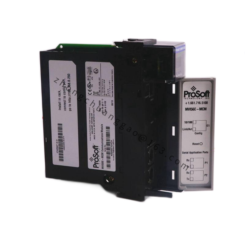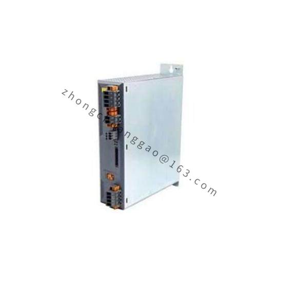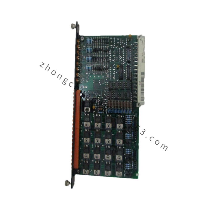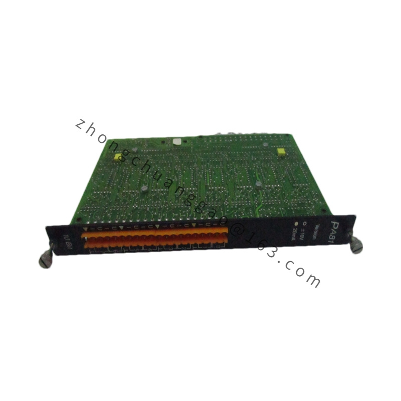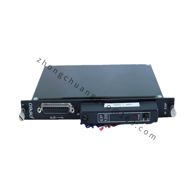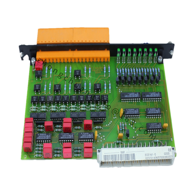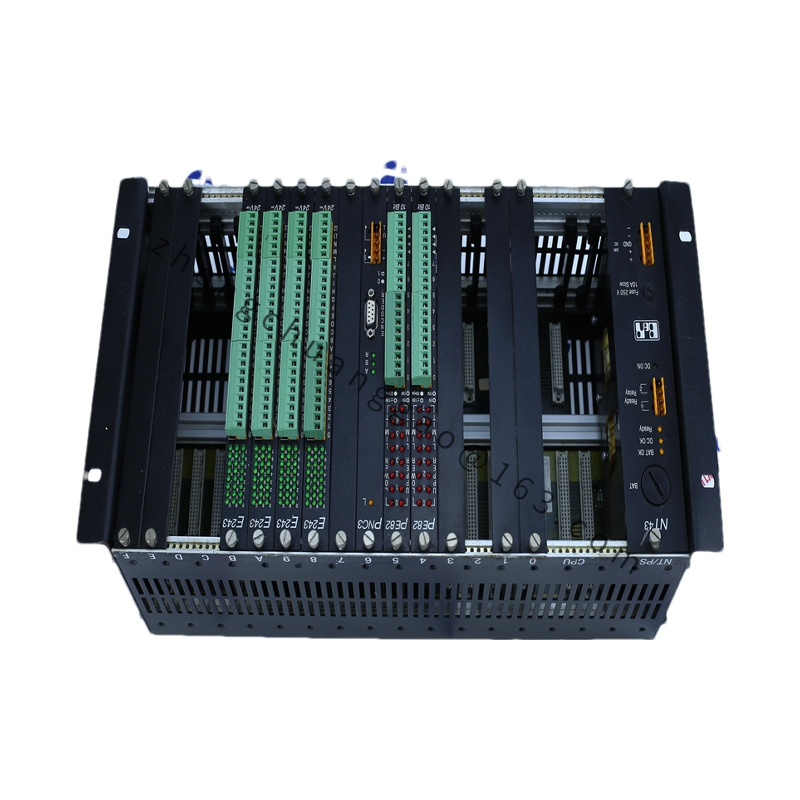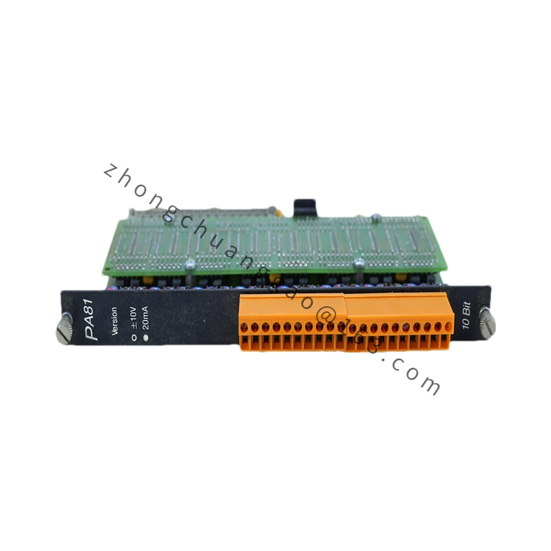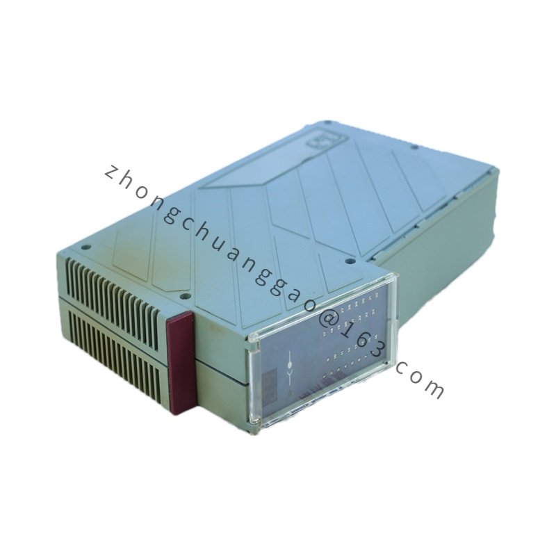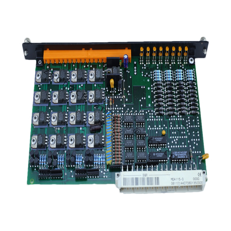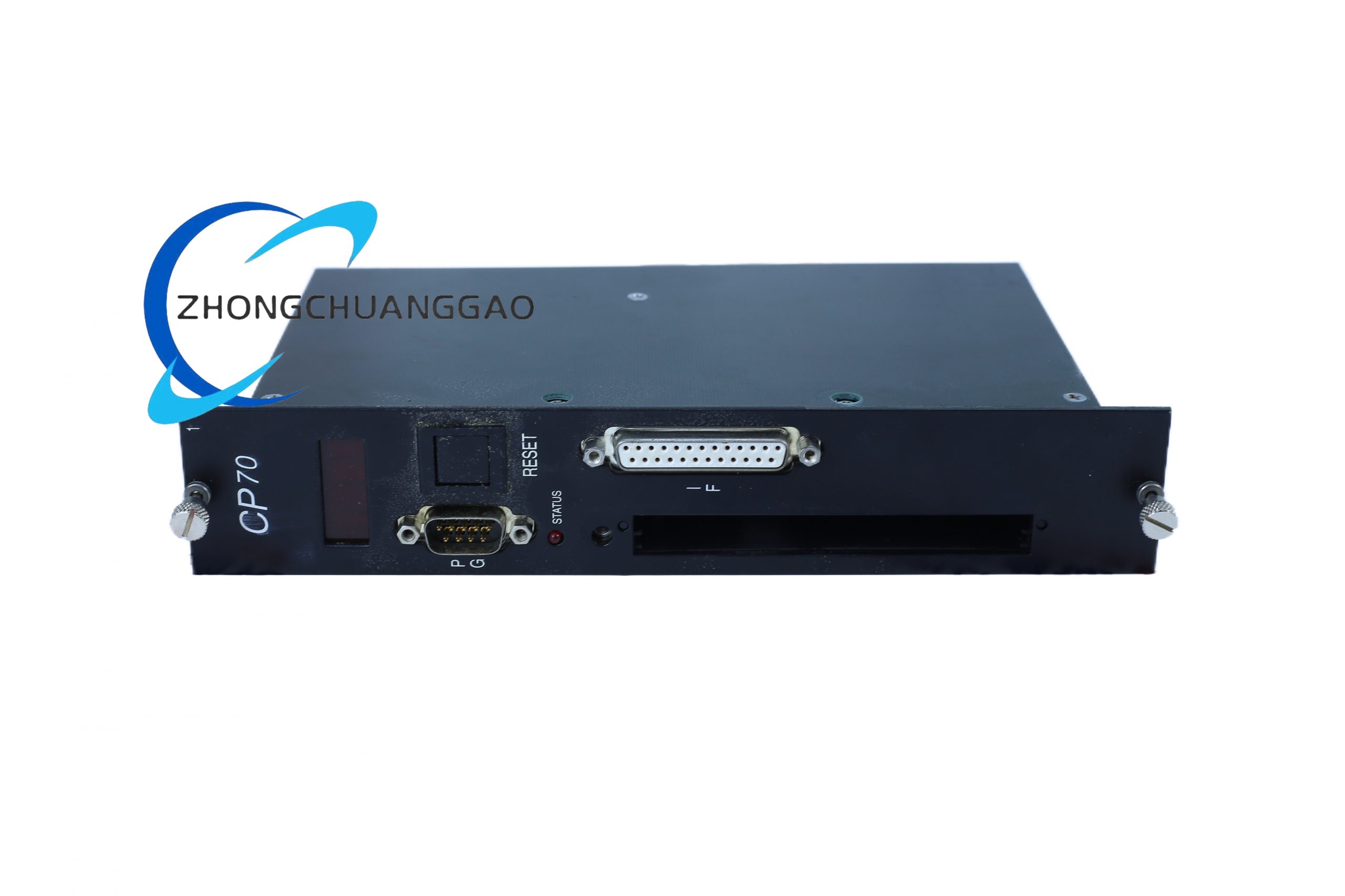

B&R 3IF681.86
Product Type: 4-Channel Analog Output Module (Voltage/Current)
Product Description:
The B&R 3IF681.86 is a 4-channel analog output module from the B&R X20 system. It generates precision voltage (0-10 V, ±10 V) or current (0-20 mA, 4-20 mA) output signals for controlling actuators, valves, inverters, and variable frequency drives.
Detailed content
Technical Specifications:
- Number of Channels: 4 analog outputs (single-ended)
- Resolution: 12-bit D/A converter
- Output Ranges (selectable per channel):
- Voltage: 0 to +10 V, ±10 V
- Current: 0 to 20 mA, 4 to 20 mA
- Output Accuracy: ±0.2% of full scale (typical at 25 °C)
- Update Rate: Up to 1 kHz (all channels simultaneously)
- Settling Time: ≤ 10 µs (to 0.01% of full scale)
- Isolation: Channel-to-channel isolation, 250 V DC; field-side to logic-side isolation, 500 V DC
- Load Capacitance: ≤ 1 nF (voltage mode)
- Bus System: X20 System Bus
- Power Supply: 24 V DC via X20 bus connector
- Power Consumption: ≤ 1.5 W
- Operating Temperature: -25 °C to +70 °C
- Protection Rating: IP20 (with X20 base/coupler)
- Dimensions (W × H × D): 25 mm × 90 mm × 75 mm
- Weight: Approximately 100 g
Functional Features:
- Per-channel range configuration via Automation Studio
- Software ramp/slew rate limiting configurable per channel
- Diagnostic functions: overcurrent, open-load, short-circuit detection
- Fail-safe output value configurable (hold last value, set to 0, set to max)
- Hot-swappable with X20 base units
Structural Characteristics:
- PA66-GF30 plastic housing, UL94 V-0
- Push-in spring terminals for 0.5 mm² to 2.5 mm² wire
- LED indicators: Power (green), Channel 0-3 (yellow), Fault (red)
- DIN rail TS 35 mounting
Material Composition:
- Housing: Glass-fiber reinforced polyamide (PA66-GF30)
- Terminals: Phosphor bronze, tin-plated
- PCB: FR-4, conformally coated
- D/A Converter IC: Analog Devices AD5764 or equivalent (16-bit internally, 12-bit used)
Applicable Industries:
- Valve positioning (pneumatic/hydraulic)
- Variable frequency drive (VFD) speed control
- Heater control (proportional)
- LED dimming / lighting control
- Process control loops
Installation Requirements:
- Mount on X20 Base (3EX280.60-1) or X20 Coupler (3EX290.60-1)
- For current output (4-20 mA): external loop power supply required (24 V DC typical)
- Use shielded twisted-pair cables; ground shield at controller end only
- Maximum cable length: 100 m (voltage), 50 m (current)
Usage Notes:
- Never short-circuit current output — permanent damage to output stage will occur
- For 4-20 mA outputs, ensure total loop resistance does not exceed (Vsupply – 8V) / 0.02A
- Verify output polarity matches field device requirements before energizing