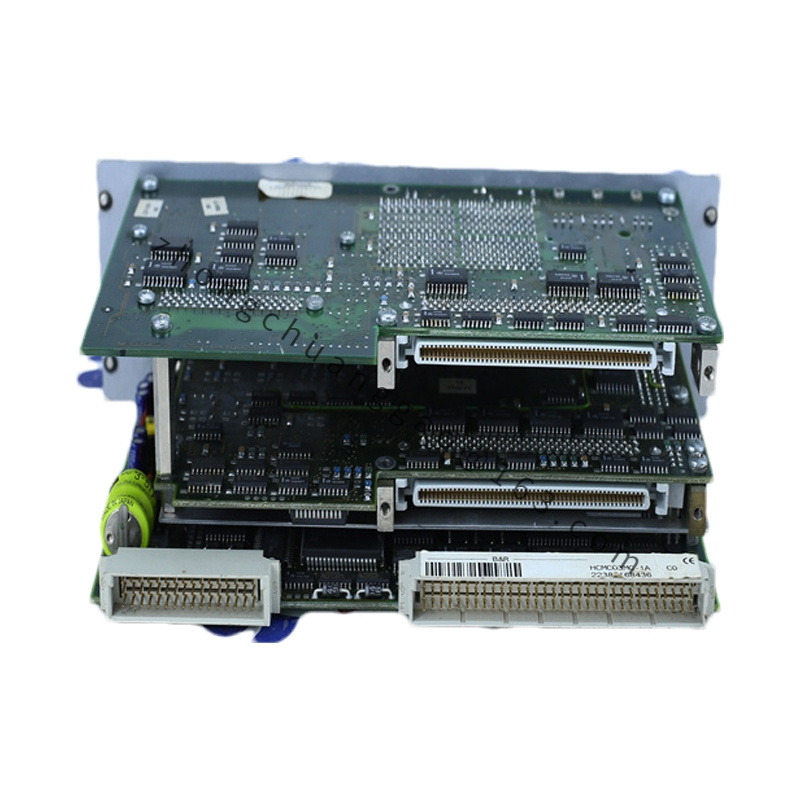
Processor Performance
0.6 microsecond basic instruction cycle.
Memory
118 KB user SRAM, 138 KB system SRAM, 512 KB FlashPROM.
RS232 Interface
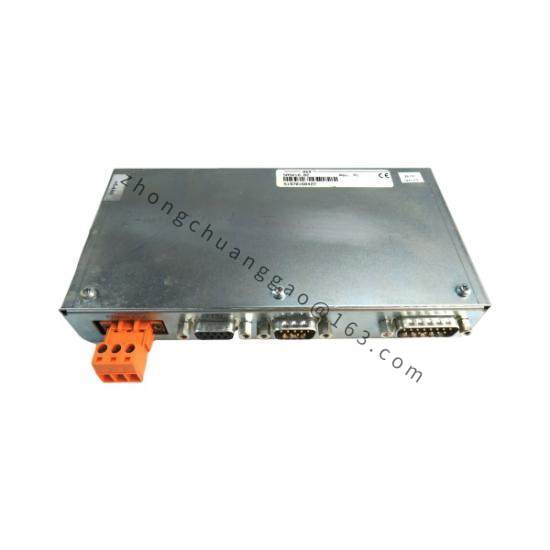
9-pin DSUB male, maximum 115.2 kbit/s, for programming, HMI, barcode readers and service communication.
CAN Interface
9-pin DSUB, electrically isolated, configurable 50 kbit/s, 250 kbit/s or 500 kbit/s, station address set by hex DIP switches.
Operating Mode
Automatic mode recognition by slot; slot 3 or 4 operates as CPU, other supported slots operate as interface processor.
Real-Time Clock
1-second resolution when buffered for CPU operation.
Data Backup
Backup through System 2005 baseplate battery or external AC240 buffer module.
Power Consumption
Maximum 4 W from 5 VDC backplane.
Status Display
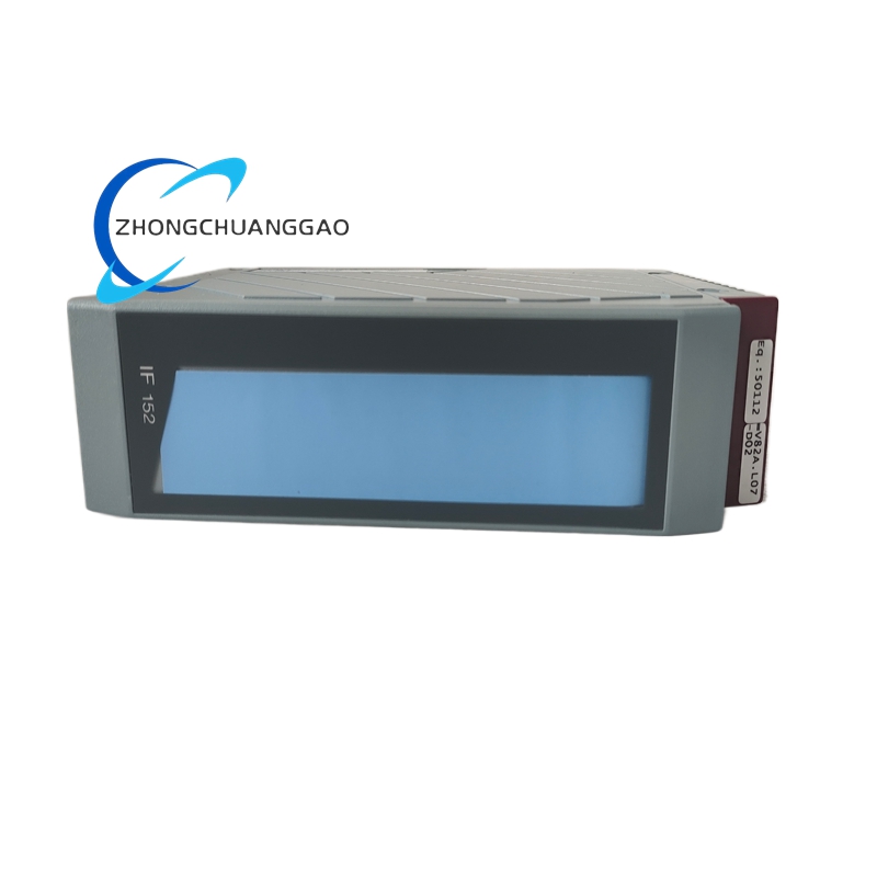
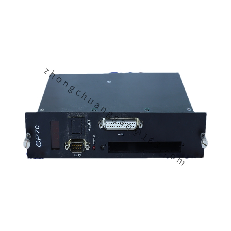
Ready, Run, Error, Mode and CAN LEDs, plus reset button.
Mechanical Dimensions
165 mm × 40 mm × 110 mm.
Housing Material
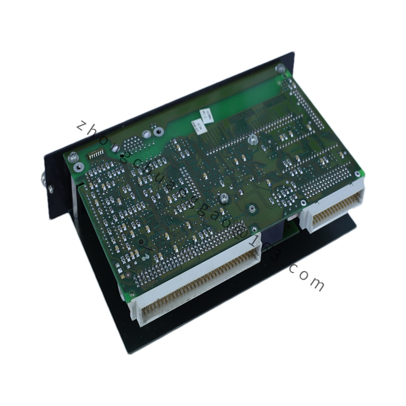
Industrial 2005 module frame, FR4 PCB, metal/plastic front cover.
Mechanical Structure
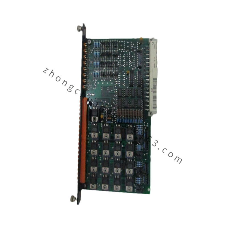
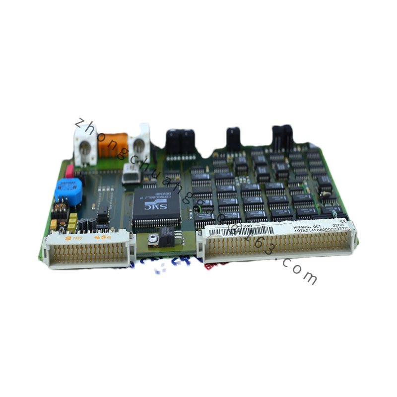
Backplane bus connector, front door with reset button, hex DIP switches, RS232 port and CAN port, LED indicator panel.
Working Principle
The onboard CPU executes PG2000 programs in STL, LAD or PL2000. The RS232 port exchanges data with programming devices, HMI panels or serial instruments. The CAN port communicates with field devices or remote I/O. Process data is mapped to the 2005 backplane and exchanged with central CPU or, in CPU mode, controls local I/O through an expansion master.
Local I/O Expansion
Use EX350 expansion master for additional 2005 baseplates when operating as CPU.
Installation Requirements
Insert the module into the correct 2005 baseplate slot according to the required CPU or interface role. Set the CAN node address with the hex switches. Use shielded CAN cable with proper termination. Install the baseplate backup battery or AC240 buffer module before commissioning.
Usage Precautions
Assign unique CAN station addresses on the same network. Program only with the approved PG2000 environment. Verify RS232 cable wiring before connecting service devices. Inspect backup battery status regularly when the module stores critical programs.