Technical Specifications
The system uses triple modular redundancy with three CPU modules. Total speed inputs are six channels, two per CPU. Discrete and process-variable inputs total 32 channels, with 12 channels configurable as discrete or 4 to 20 milliampere analog. Relay output modules provide five relays each, including trip and status relays. Recorder outputs are two internally powered 4 to 20 milliampere channels per CPU. Power requirement for related base and I/O termination is 24 volt direct current nominal, with wider AC/DC configurations available depending on system power module.
Functional Features
Graphical logic programming configures overspeed trips, voting schemes, alarm relays, and recorder outputs. Self-diagnostics monitor CPUs, inputs, outputs, and communication. De-energize-to-trip programming ensures shutdown on power loss. The terminal base preserves field wiring during controller service.
Compliance And Safety
The platform targets SIL 3 capability, API 670 and API 612 machinery protection practices, IEC 61508 functional safety, CE machinery and electromagnetic compatibility requirements, and CSA plus hazardous-area certifications for applicable variants.
Material Composition
The controller modules use industrial printed-circuit boards, metal front panels, and molded terminal blocks. The terminal base uses flame-retardant industrial enclosure materials with tinned copper terminals and labeled wiring bars.
Structural Characteristics
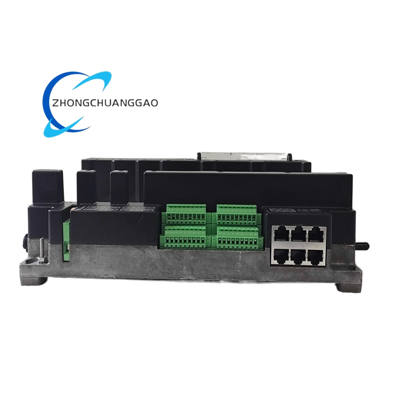
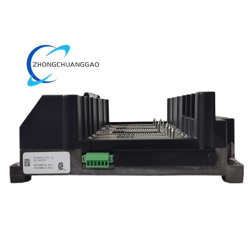
The 3701/55 system mounts as standalone rack or panel assemblies. The 289761-01 base provides fixed terminals for speed sensors, discrete inputs, analog inputs, relay outputs, communication, and power. Module slot design allows hot standby service when the system configuration supports it.
Working Principle
Speed sensors produce pulse or sinusoidal signals. CPUs convert frequency to speed, compare values to configurable setpoints, and execute voting logic. Validated trip commands energize or de-energize shutdown relays that isolate turbines, compressors, or driven equipment.
Installation Requirements
Mount the terminal base in a clean control cabinet with adequate clearance. Ground the base and shield all sensor cables. Use approved speed probes and calibrated 4 to 20 milliampere transmitters for analog channels. Verify wiring against the 3701/55 loop diagram before applying power.
Usage Precautions
Confirm SIL voting mode before startup. Test trip relays during planned outages. Keep firmware and configuration backups. Do not bypass overspeed protection during commissioning.


.jpg)

