Technical Specifications
Control supply: 85-264 VAC/DC according to listed technical data.
Field output: 0-200 VDC, 0-20 A DC continuous.
Peak field current: 300% of rated for 10 seconds according to listed forcing data.
Control hardware: dual-core DSP and FPGA according to published configuration.
Sampling accuracy: voltage/current ±0.1% full scale, frequency ±0.01 Hz.
Communication: 2 Ethernet ports, 2 RS485 ports, USB according to configuration; protocols include Modbus TCP, Modbus RTU and IEC 61850 according to enabled options.
I/O expansion: 8-slot modular expansion for AI, AO, DI and DO according to system configuration.
Functional Features
Automatic voltage regulation with adaptive PID control.
Power system stabilizer, reactive compensation, V/Hz limiting and excitation protection.
Hot-swappable I/O cards according to modular configuration.
Event recording, oscillography and remote parameter management.
Parallel operation, load sharing and grid-code functions according to enabled options.
Performance Parameters
Voltage build-up time: below 0.5 s to 95% rated voltage according to documented test condition.
Control cycle: 1 ms or faster according to configuration.
Voltage regulation accuracy: maintains tight generator terminal regulation under grid disturbances when properly tuned.
Operating temperature: -40°C to +70°C.
Front protection: IP52 for front panel according to listed version.
Material Composition
Reinforced control enclosure with modular I/O slots.
DSP/FPGA control boards, communication boards and isolating interfaces.
Thyristor or switched field power stage according to output class.
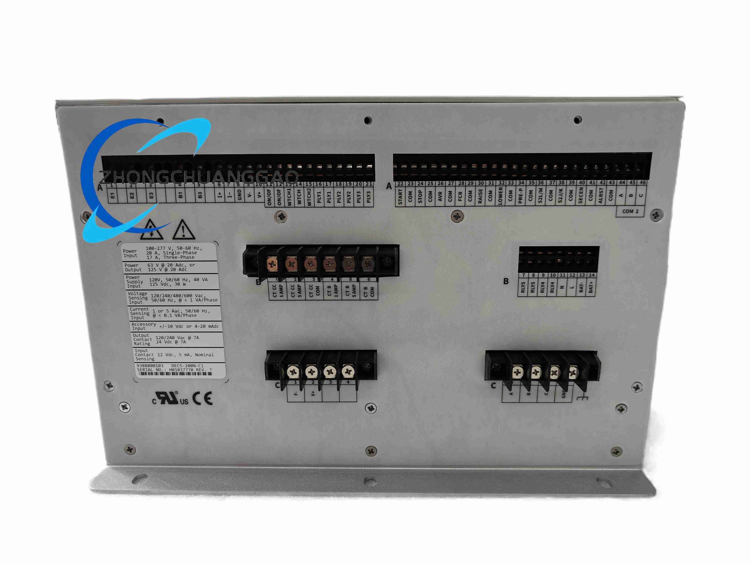
Shielded terminals for PT, CT, field and auxiliary wiring.
Structural Features
Panel or cubicle mounting with accessible front display and service ports.
Modular I/O card bays for expansion.
Separated sensing, field, communication and auxiliary power sections.
Working Principle
Generator voltage, current and frequency signals are digitized and processed by the DSP/FPGA control core. The controller calculates AVR, var, power factor or field-current error, applies stabilizing and limiting algorithms, and drives the field power stage. Communication ports provide setpoint control, metering, event data and integration with plant control systems.
Installation Requirements
Install in a controlled cubicle with adequate cooling and access clearance.
Enter correct PT ratio, CT ratio, generator rating and field parameters before startup.
Use separate shielded cables for voltage sensing, current sensing and communication.
Terminate RS485 buses with 120 Ω resistors only at physical ends.
Ground shielding at one point to avoid ground loops.
Usage Precautions
Verify field voltage and current ratings against generator exciter design.
Test over/undervoltage, over/underfrequency, loss-of-field and V/Hz limiters before service.
Update firmware only with stable auxiliary power and approved configuration file.
Do not operate with open PT secondary or shorted CT secondary.
Disconnect field and control power before replacing I/O or power modules.