Technical Specifications
Field voltage output options: 32 VDC, 63 VDC or 125 VDC.
Continuous field current: 15 A DC.
Forcing capability: up to two times output for 10 seconds according to output class and conditions.
Regulation accuracy: ±0.25% in AVR mode.
Sensing: single-phase or three-phase true RMS voltage; current sensing 1 A or 5 A.
Control supply options: 16-60 VDC, 30 W; 85-132 VAC, 50 VA; or 90-150 VDC, 30 W according to order code.
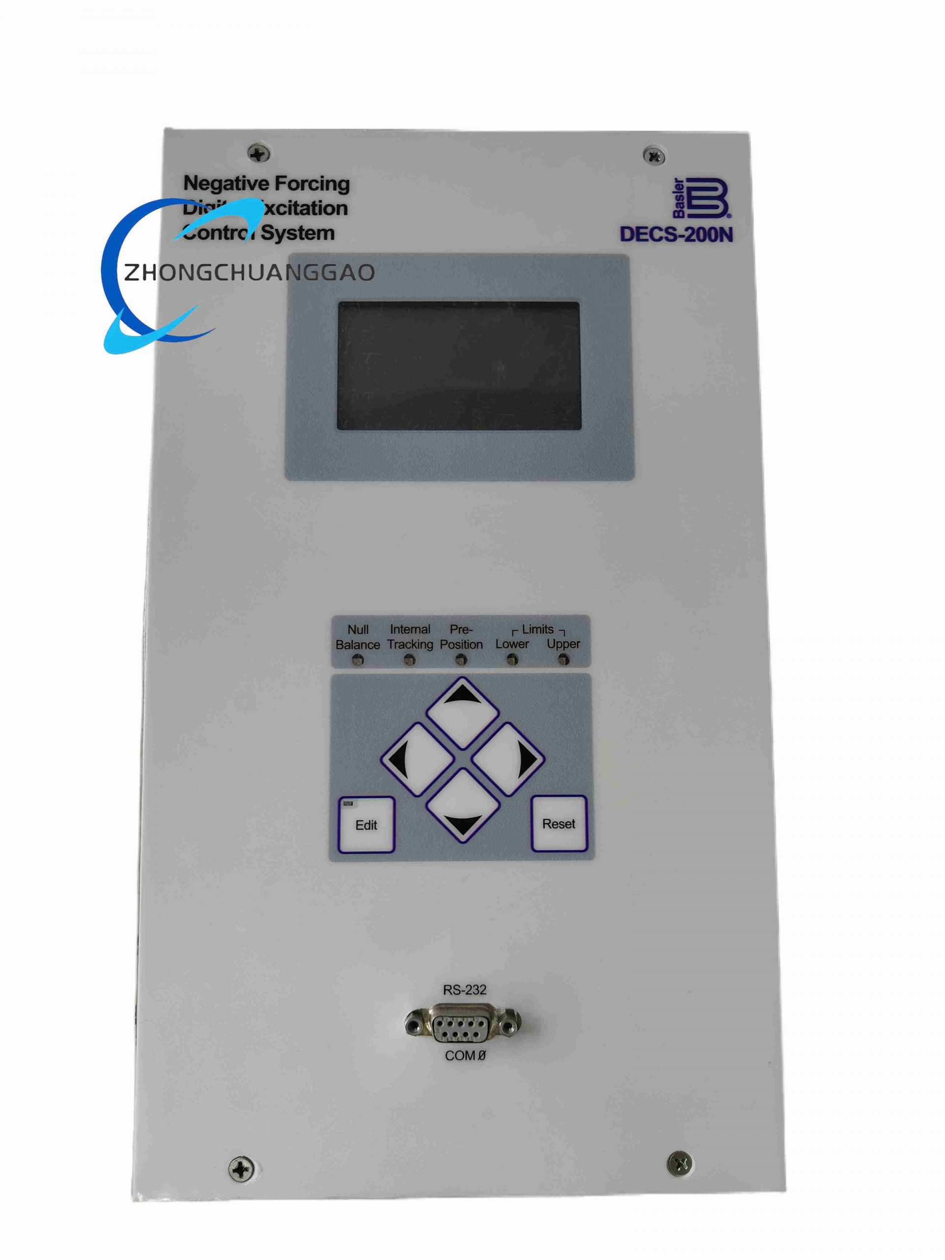
Communication: COM0 RS232 front, COM1 RS232 side, COM2 RS485 Modbus RTU.
Functional Features
AVR, VAR/power factor, field current regulation and mode tracking.
Overvoltage, undervoltage, field overcurrent, minimum/maximum excitation, under/overexcitation and stator current limiting.
Exciter diode monitoring, watchdog and loss-of-field protection.
Sequence-of-event recording and oscillography according to configuration.
Autotracking between inactive and active control modes.
Performance Parameters
Metering accuracy: below 1% for approximately 12 generator parameters according to controller configuration.
RS485 communication distance: approximately 4000 ft with proper cable and termination.
Operating temperature: -40°C to +60°C.
Standards: CE, UL recognition and IEEE C37.90.1 surge/transient compliance according to listed versions.
Material Composition
Industrial excitation enclosure with control PCB, communication interface and power stage.
SCR/thyristor or switched field power devices according to output class.
Optoisolators, metering circuits and relay/alarm outputs.
Shielded terminals for PT, CT, field and control wiring.
Structural Features
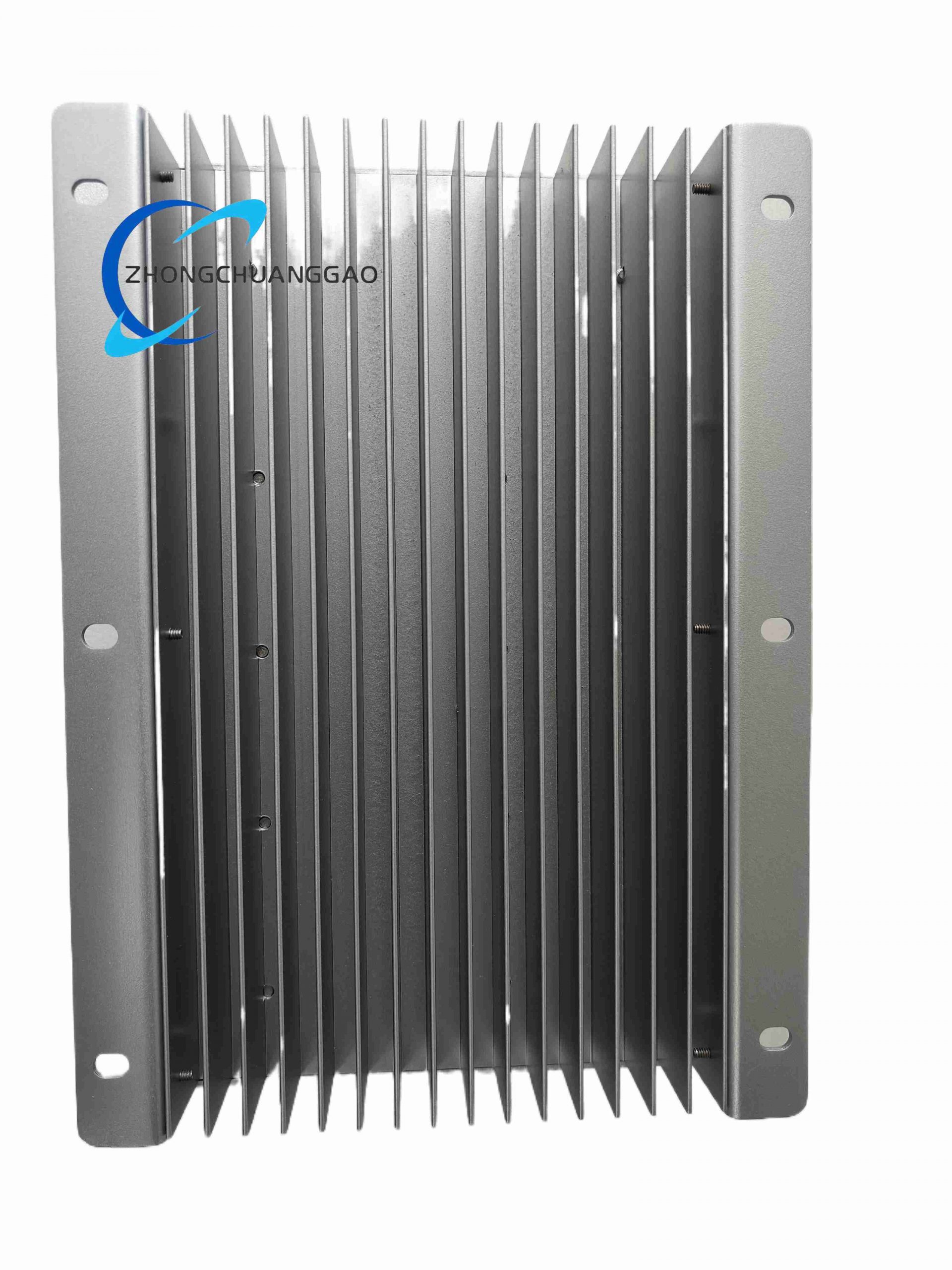
Panel or cabinet mounting with front communication and configuration access.
Separated sensing inputs, field outputs and digital/analog I/O terminals.
Status display, keypad or software configuration interface.
Working Principle
Generator voltage and current are sampled through true RMS measurement. The controller computes voltage error and selected control-mode error, applies PID or adaptive regulation, and drives the field power stage. Communication ports provide setpoint commands, metering data and protection status to external control systems.
Installation Requirements
Install in a controlled environment with adequate ventilation and vibration isolation.
Match field voltage/current class with generator exciter specification.
Use shielded cables for PT and CT circuits; separate them from power conductors.
Configure Modbus address, baud rate and termination for RS485 network.
Validate grounding for common reference, shunts and cable shields.
Usage Precautions
Do not exceed 15 A continuous field output unless the ordered class specifies higher rating.
Verify all protection setpoints before closing field breaker.
Test exciter diode monitoring, field overcurrent and undervoltage functions during commissioning.
Keep configuration backup for rapid replacement.
Disconnect AC/DC control and field power before terminal maintenance.