Technical Specifications
Voltage regulation accuracy: ±0.25%.
Field output options: 32 VDC, 63 VDC or 125 VDC classes.
Continuous field current: up to 15 A DC according to output rating; selected 1L listings state 10 A continuous with 15 A maximum depending on order configuration.
Sensing: single-phase or three-phase true RMS voltage and current.
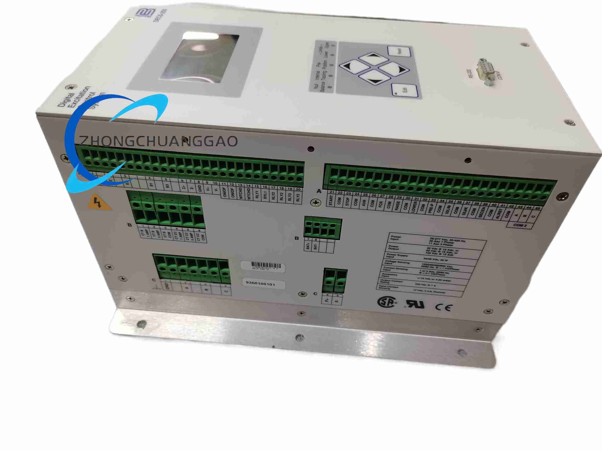
Control supply options: 24/48 VDC, 30 W or AC sensing/auxiliary supply according to order code; listed 1L variants include 11/20 A, 1-3 phase, 56-277 VAC, 50-400 Hz sensing/control input configurations.
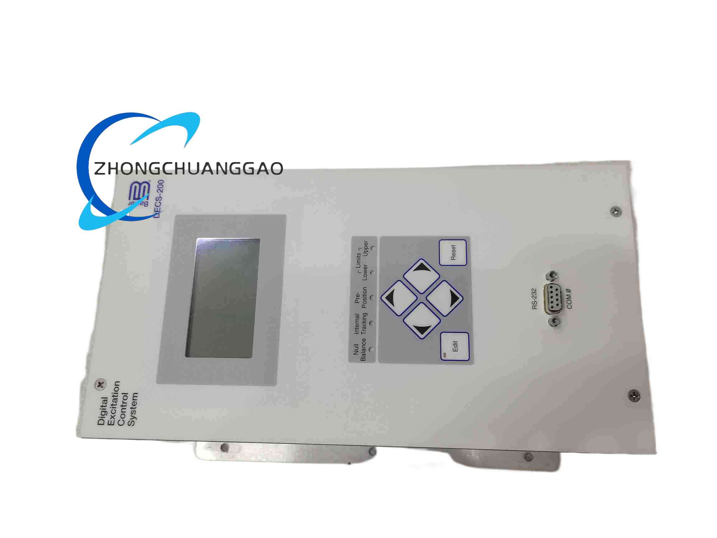
Communication: RS232 and RS485 Modbus according to configuration.
Functional Features
Automatic voltage regulation, field current regulation, VAR control and power factor control.
Soft-start, V/Hz limiting, underfrequency compensation and autotracking.
Remote setpoint through contact inputs, 4-20 mA or ±10 VDC.
Paralleling compensation and load sharing according to enabled configuration.
Front panel or PC software configuration.
Performance Parameters
Protection functions: overvoltage, undervoltage, overfrequency, underfrequency, reverse power, maximum/minimum excitation limits.
Metering: generator voltage, current, frequency, field current and active/reactive parameters.
Operating temperature: -40°C to +70°C according to listed 1L technical data.
Regulation response suitable for standby diesel, hydro and industrial generator sets.
Material Composition
Industrial control enclosure for panel mounting.
PCB assemblies with DSP or microcontroller, sensing circuitry and communication interfaces.
Thyristor or switched-mode field power stage according to output voltage/current class.
Shielded terminal assemblies for PT, CT, field and control wiring.
Structural Features
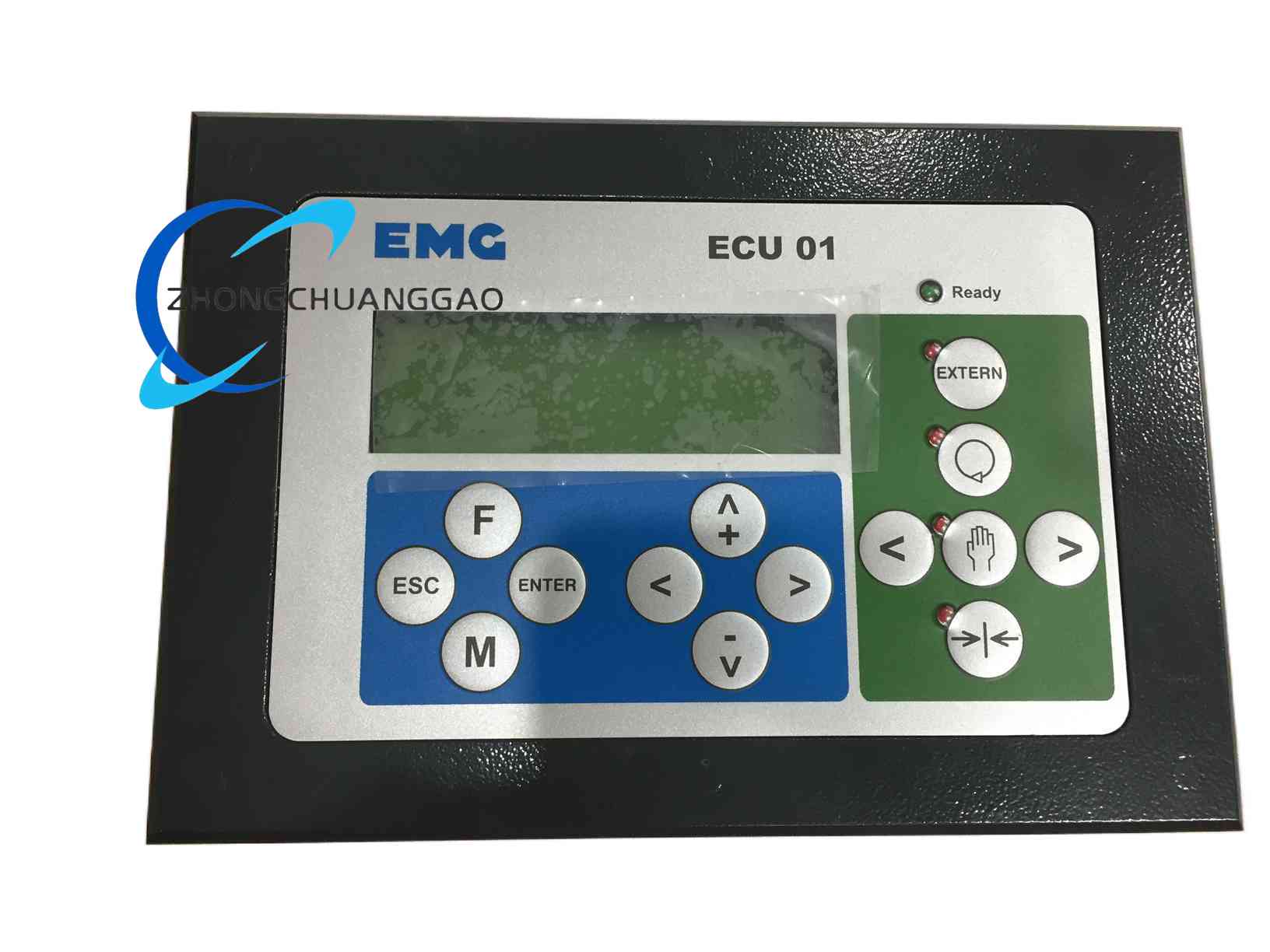
Compact excitation controller housing with front display or status interface according to version.
Separated sensing, field output, control input and communication terminals.
DIP, keypad or software parameter access.
Working Principle
The controller measures generator terminal voltage and current through PT and CT inputs. It calculates error between actual and desired voltage, applies PID or adaptive control, and adjusts field excitation through the power stage. Increased excitation raises generator voltage; reduced excitation lowers voltage. Current, VAR, power factor and limiting functions modify the control output according to selected mode.
Installation Requirements
Mount in a ventilated control cabinet with clearance for wiring and cooling.
Verify PT ratio, CT ratio, field voltage and field current before configuration.
Use shielded twisted pair for voltage and current sensing; ground shield at one point.
Connect field output to exciter or static excitation winding according to generator design.
Set communication parameters before connecting to SCADA or PLC.
Usage Precautions
Do not apply PT secondary voltage above the rated sensing input.
Confirm generator field resistance and minimum field voltage before selecting output class.
Test protection functions during commissioning before parallel operation.
Back up configuration after final tuning.
Disconnect field and sensing circuits before performing hardware maintenance.