Technical Specifications: F05 ISO 5211 dimensions include a minimum flange diameter of 65 mm, central spigot diameter 35 mm, bolt circle diameter 50 mm, 4 holes with M6 threads and maximum flange height per actuator drawing. The standardized F05 torque rating is 125 Nm. Drive geometry must be confirmed from the actuator drawing and may use square, double-D or keyed interface according to FH03 detail.
Functional Features: The flange enables direct interchange between F05-compatible actuators and valves. It maintains bolt pattern alignment, stem centering and torque transmission without custom machining. The assembly supports quarter-turn automation for isolation and control duties.
Performance Parameters: Maximum flange interface torque is 125 Nm under ISO 5211 with M6 bolts at standard tightening values. Final actuator selection must also respect the valve stem allowable torque, which can be lower than the flange rating.
Material Composition: Mounting pads and brackets use galvanized steel, stainless steel or aluminum alloy depending on the actuator construction. Fasteners use zinc-plated or stainless steel. Drive inserts use steel or stainless steel.
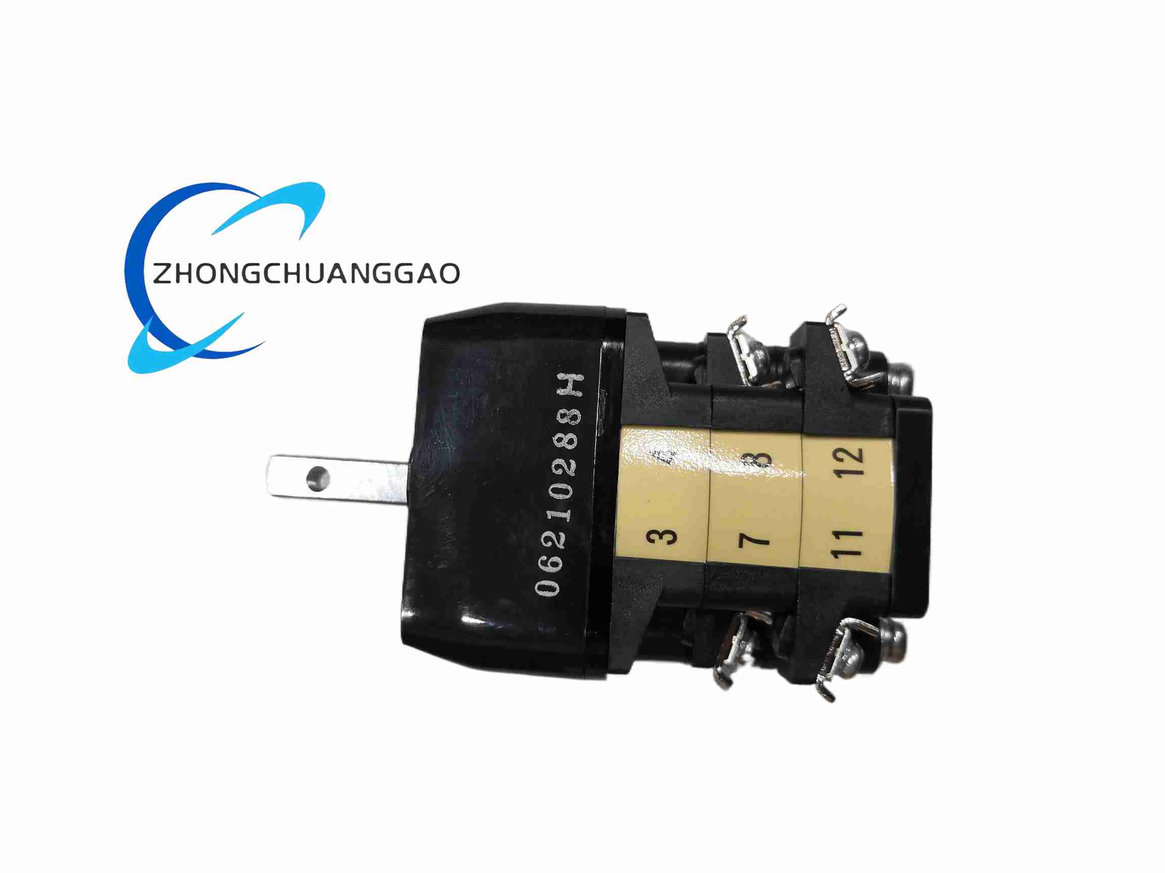
Structural Characteristics: The unit consists of an F05 bolt pattern, central locating spigot, drive coupling recess or square/keyway, and preloaded hardware where supplied. FH03 defines hole pattern, drive form and overall stack height stated on the AR501 drawing.
Working Principle: Actuator rotation transfers torque through the F05 flange and drive interface to the valve stem. The bolt circle resists overturning forces, the spigot maintains concentricity, and the drive profile converts rotary motion into quarter-turn valve operation.
Installation Requirements: Clean the valve and actuator mating faces. Align the spigot, insert four M6 bolts in the F05 circle and tighten to the torque specified by the actuator and valve manufacturers. Confirm stem engagement depth, square size or keyway position before final bolt tightening.
Usage Precautions: Never exceed 125 Nm flange rating and never exceed the valve stem allowable torque. Verify actuator and valve share F05 pattern and identical drive profile. Recheck bolt torque after initial operating cycles and after any actuator replacement.