Digital guide

You are here:

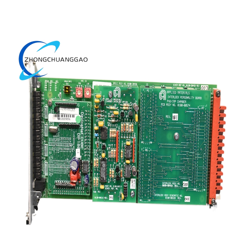
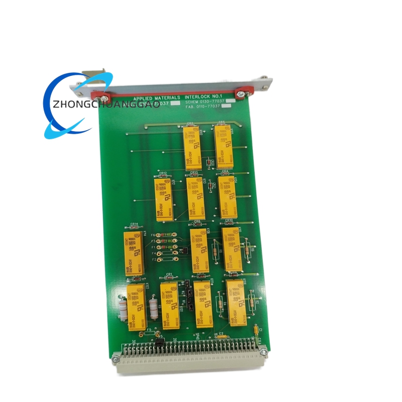
AMAT 0100-77037

Product Name​
Interlock and process control PCB assembly for PVD/etch semiconductor tools.
Product Introduction​
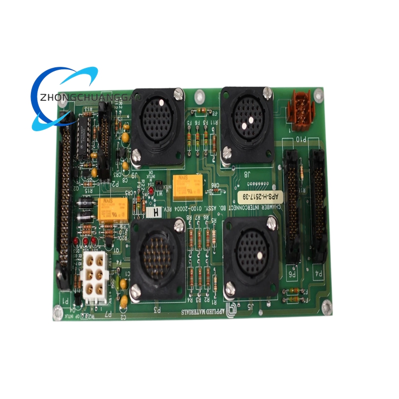
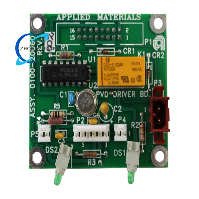
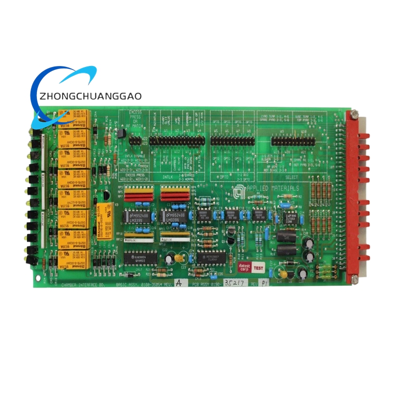
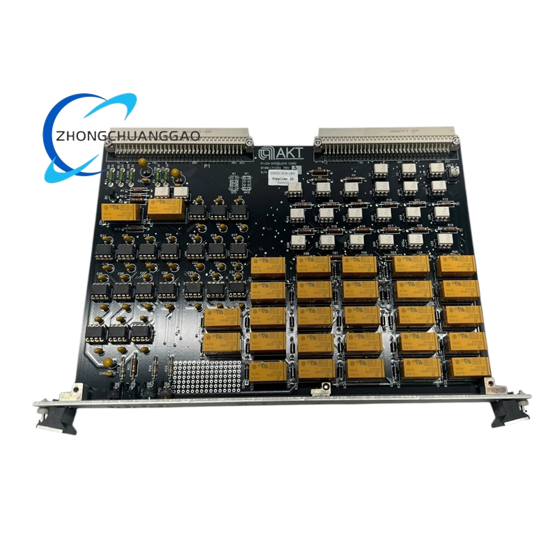
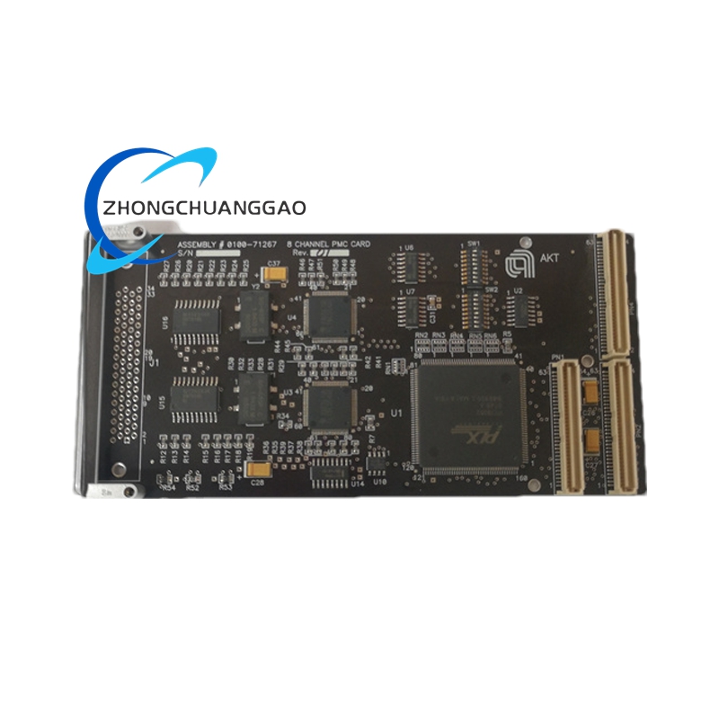
Applied Materials 0100-77037 appears in public spare-part sources as an interlock PCB, chamber safety board, or PVD process control assembly. It is used for digital signal acquisition, safety interlock logic, chamber sequencing, and process variable monitoring in AMAT vacuum platforms.
Detailed content

Technical Specifications​
  • Manufacturer: Applied Materials
  • Type: interlock PCB / process control board / I/O safety assembly depending on listing
  • Voltage: 5 VDC and 24 VDC from backplane or power module
  • I/O: digital input/output in interlock listings; analog acquisition for pressure, temperature, power in PVD listings
  • Communication: internal proprietary bus, RS422/discrete I/O in selected interlock listings, SECS/GEM in selected process listings
  • Operating temperature: 0–50°C
  • Storage temperature: -20–85°C in selected listings
  • Isolation: up to 2500 V descriptions in selected interlock sources
  • Coating: conformal coating for chemical-environment protection in selected listings
  • Dimensions: approximately 6.5 × 4.5 × 0.8 in in selected interlock listings
  • Compliance: SEMI S2/S8, CE, UL, RoHS in selected listings
Function Features​
  • Monitors door, lid, vacuum, gas, RF, and emergency-stop states
  • Executes safety voting and fail-safe output control
  • Collects chamber pressure, temperature, and power data in process variants
  • Provides ADC-based signal conditioning and fault diagnostics
  • Supports closed-loop interlock response for semiconductor process equipment
Application Scenarios​
  • AMAT Endura and Centura PVD systems
  • Centura etch and chamber safety interlock applications
  • Mirra CMP and related semiconductor platforms in selected listings
  • Vacuum chamber sequencing, gas-admission control, RF enable/disable logic
Material Composition​
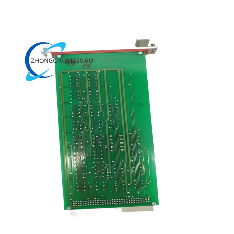
  • Substrate: multilayer FR-4 with conformal coating in selected variants
  • Relays/optocouplers: safety-rated isolation components
  • Connectors: high-density backplane and D-sub/fiber options depending on configuration
  • Housing: open card format or subrack-protected assembly
Structural Characteristics​
  • Plug-in PCB with standoff or subrack mount
  • LED indicators for power, communication, and channel status in selected variants
  • Screw-terminal or edge-connector interfaces depending on configuration
  • Dedicated safety-circuit sections separated from general I/O
Working Principle​
Safety inputs are conditioned and compared against predefined thresholds. The logic circuit validates door/lid/vacuum/gas states, then enables or removes power to hazardous subsystems. In process variants, sensor signals are digitized and transmitted to the controller for chamber control and interlock supervision.
Installation Requirements​
  • Install in designated chassis slot or standoff location per AMAT schematic
  • Verify all safety inputs before applying RF, gas, or heating power
  • Use correct backplane voltage and grounding scheme
  • Perform functional interlock test after installation
Usage Notes​
  • Do not bypass safety contacts or force outputs during testing
  • Do not hot-swap in powered racks
  • Inspect conformal coating and connector pins before reuse
  • Validate emergency-stop, door, and vacuum interlocks during every PM cycle

You may also like