Technical Specifications
Brand: ALSTOM / VAMP
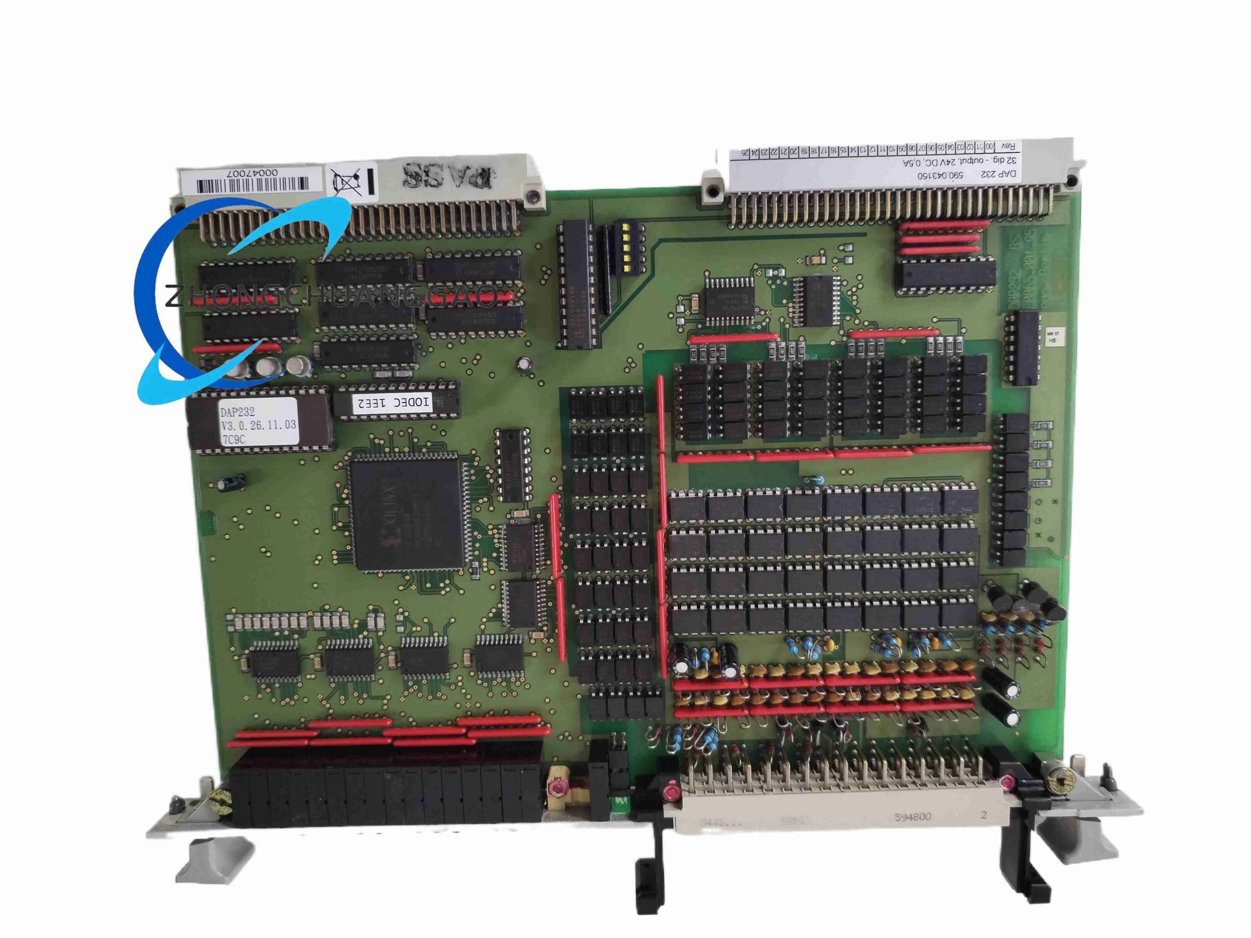
Model: DAP232
Reference Shown: 590
Product Type: Digital protection and automation relay
Application Class: Medium-voltage distribution protection
Protection Functions: Overcurrent, earth fault, directional protection, and auto-reclosing
Measurement Parameters: Current, voltage, frequency, active power, reactive power, power factor, and energy
Communication Protocols: IEC 60870-5-101/104, DNP3.0, and Modbus, per available technical information
Recording Functions: Event recording and fault recording
Installation Form: Panel or cubicle mounting
Functional Features
Feeder Protection: Detects faults and initiates tripping or alarm actions.
Earth-Fault Protection: Monitors residual or earth-fault conditions.
Auto-Reclosing: Supports automatic reclosing after transient faults.
Measurement: Provides comprehensive electrical metering.
Event and Fault Records: Stores operational events and fault data for analysis.
Substation Integration: Communicates with SCADA and protection management systems.
Application Scenarios
Medium-voltage feeders: Overcurrent and earth-fault protection
Cables and lines: Distribution network protection and automation
Transformers: Protection and monitoring functions
Switchgear: Integration into medium-voltage cubicles and control panels
Utility substations: Protection, control, and remote communication
Material Composition
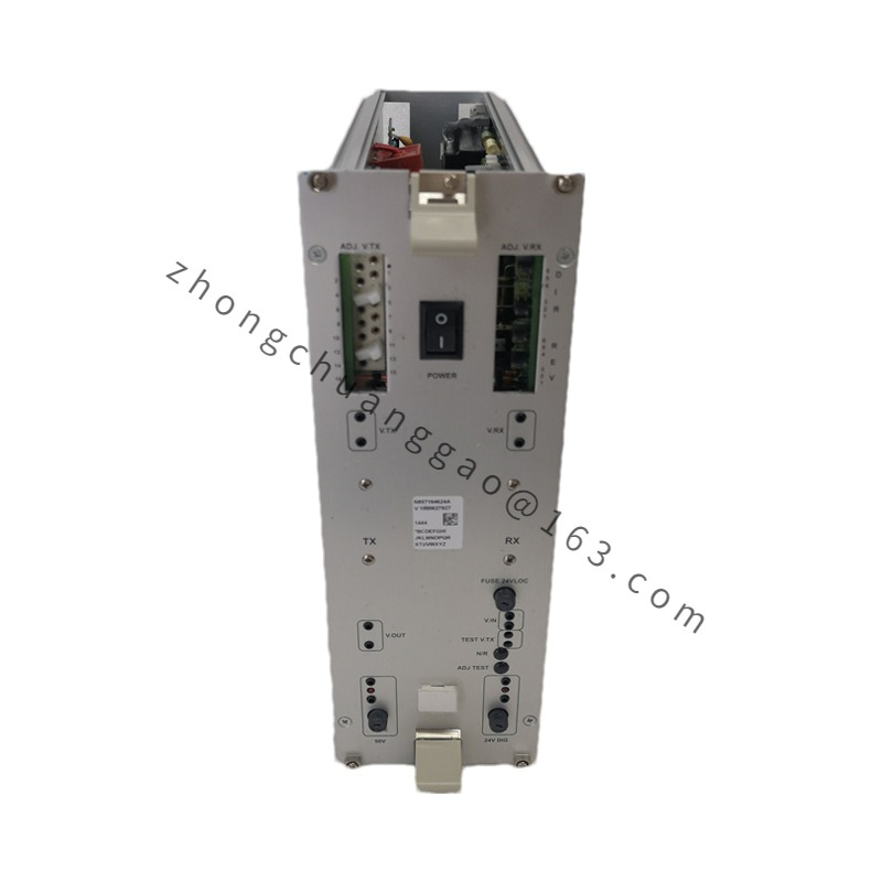
Enclosure: Industrial-grade housing with front display and keypad
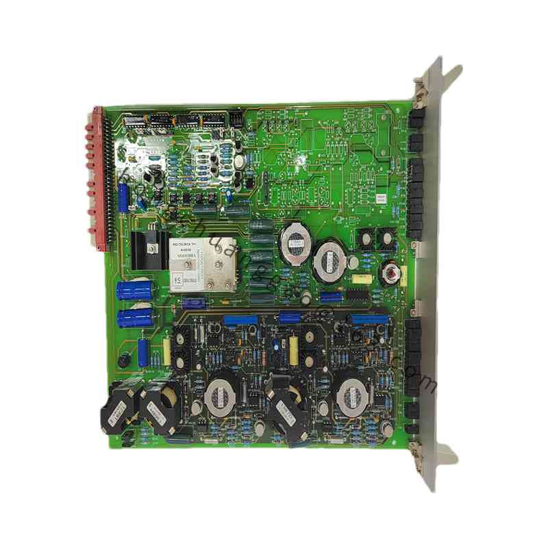
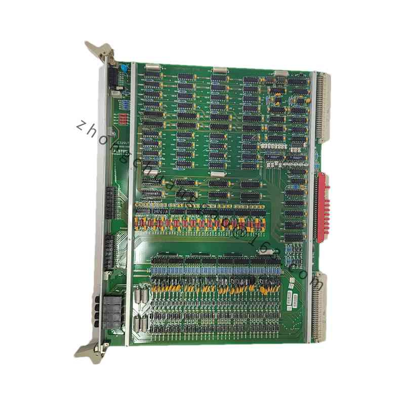
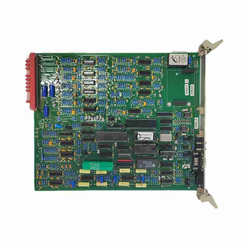
Internal Electronics: Printed circuit boards, processors, measurement circuits, and communication interfaces
Terminals: Current, voltage, binary input/output, and communication terminal assemblies
Structural Characteristics
Front Interface: Display and control keys for local operation
Rear or Bottom Connections: Current, voltage, binary, and communication terminals
Mounting Format: Designed for panel or switchgear cubicle installation
Modular Internal Design: Contains dedicated measurement, protection, and communication circuitry
Working Principle
Voltage and current transformers supply secondary signals to the relay. The internal protection algorithms continuously evaluate these measurements against configured settings. When a fault condition is detected, the relay issues trip or alarm commands and records event data for later analysis.
Installation Requirements
Voltage Class: Confirm compatibility with the actual system voltage and CT/VT ratios.
Current Transformer Ratio: Program protection settings according to the CT ratio.
Grounding: Establish proper equipment and CT grounding.
Separation: Route communication cables separately from high-voltage wiring where possible.
Enclosure Mounting: Install in a suitable panel or cubicle with adequate access for wiring and commissioning.
Settings Verification: Enter and verify all protection settings before energizing the circuit.
Usage Precautions
Authorization: Only qualified protection engineers should modify settings or perform commissioning.
Functional Testing: Perform wiring, setting, and tripping tests before placing the relay in service.
Time Synchronization: Where required, provide GPS or network time synchronization for event records.
Backup: Maintain secure records of configuration, settings, and firmware information.
Safety Procedures: De-energize equipment and follow site safety rules during installation and maintenance.