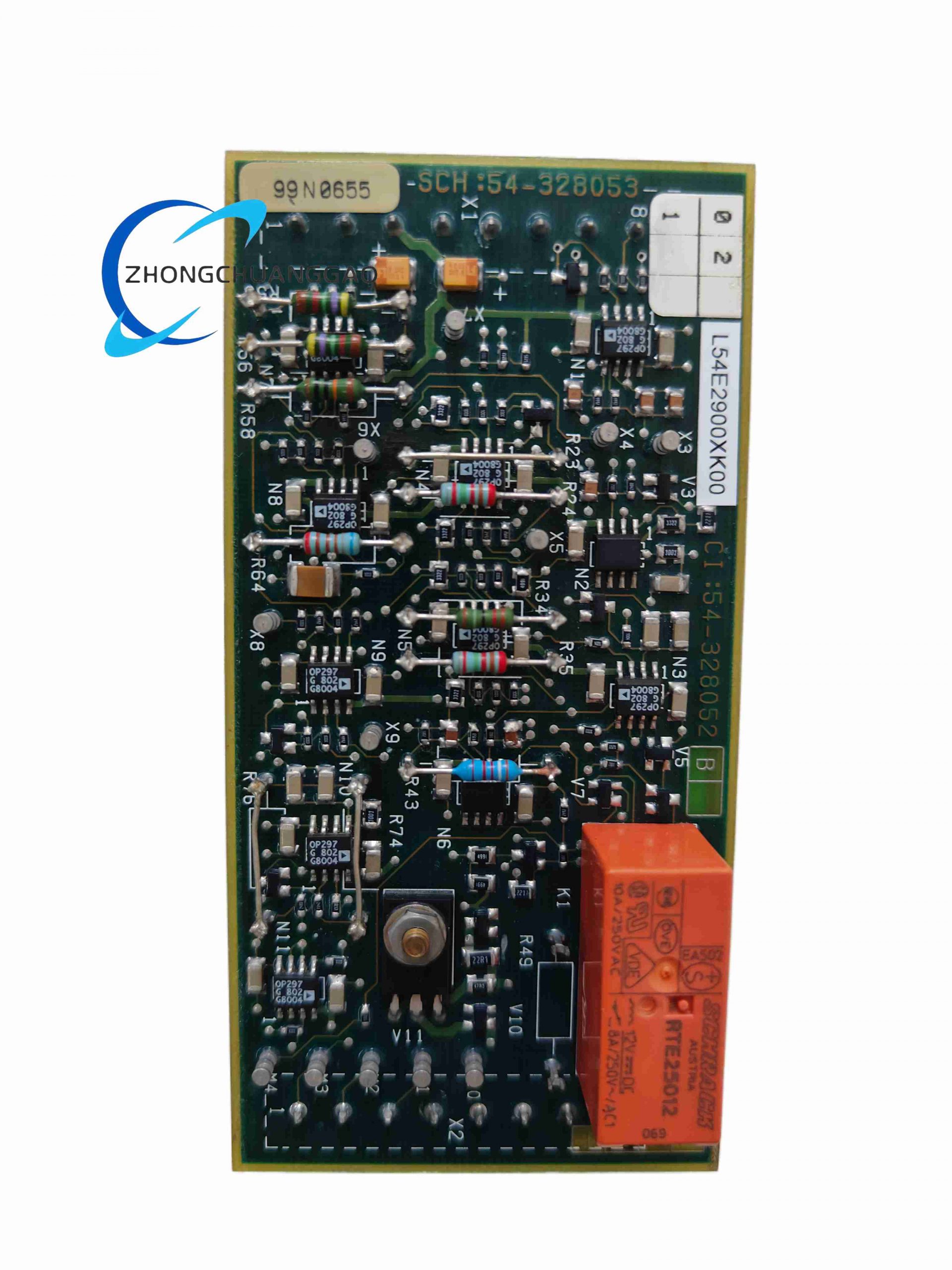
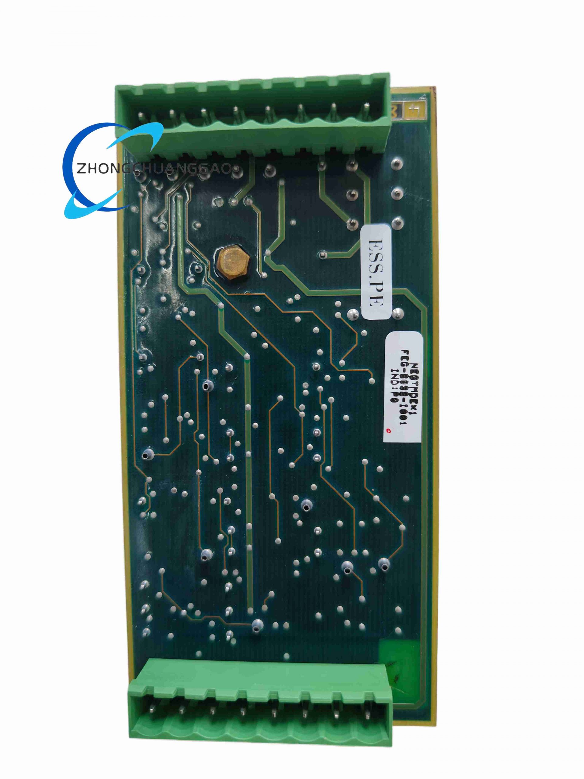
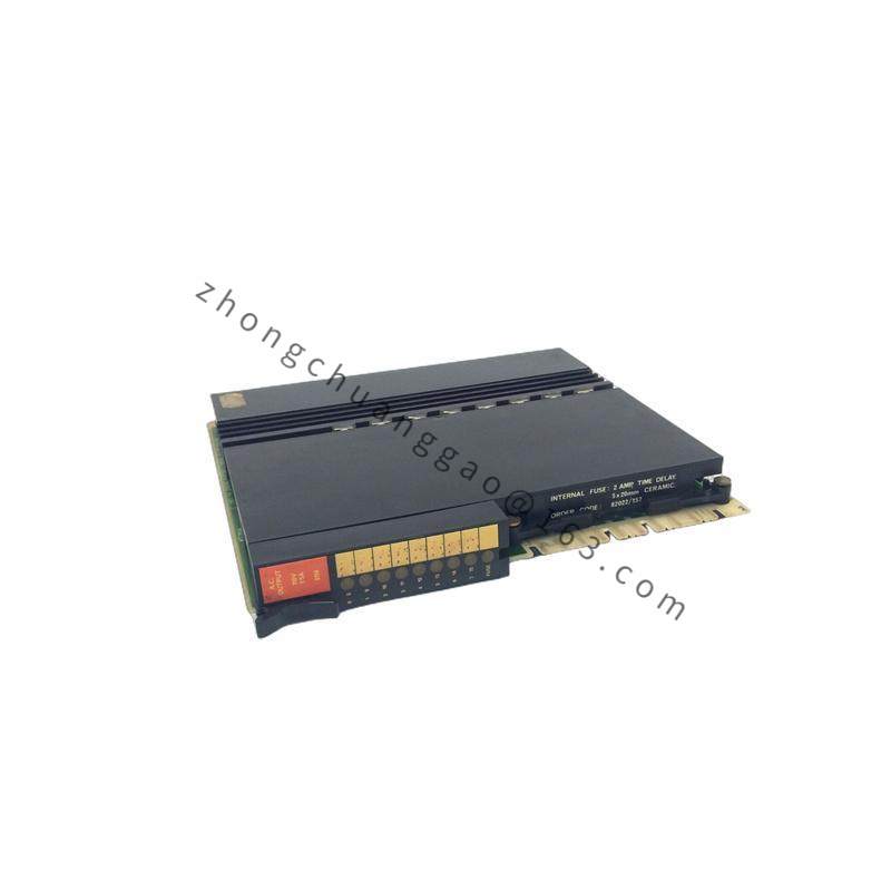
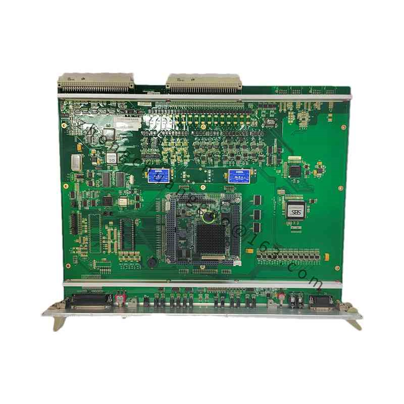
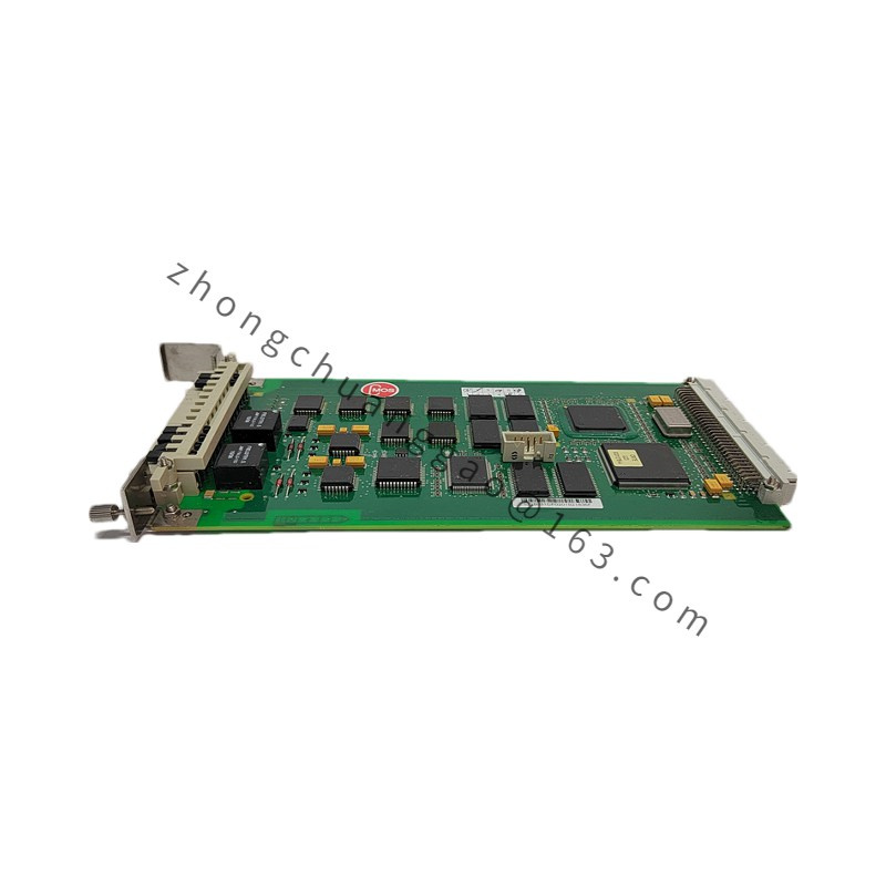
Overview
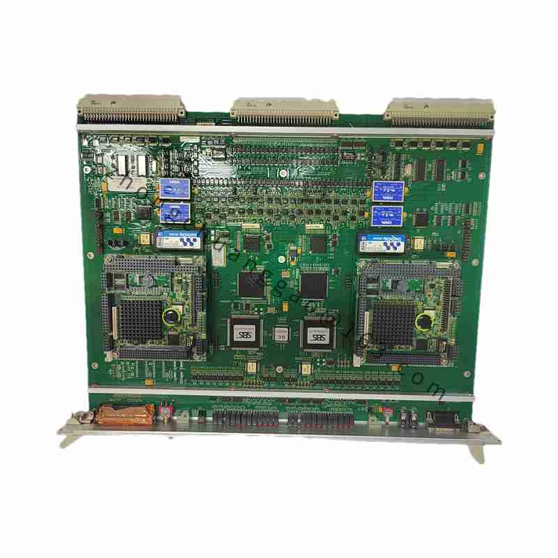
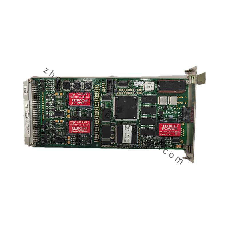
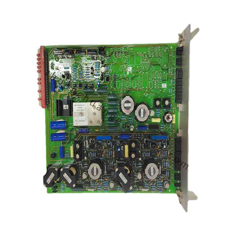
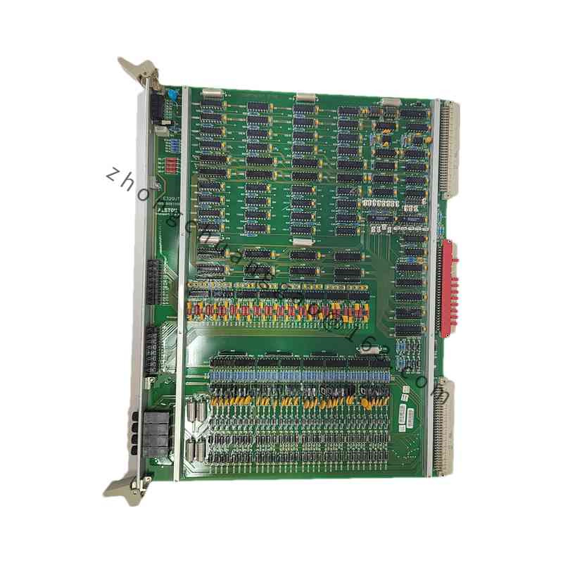
The module performs closed-loop generator voltage control, field-current management, CT/VT signal acquisition, and communication with excitation racks. It is used in steam, hydro, gas and industrial generator excitation systems where stable voltage and fast response are required.
Technical Specifications
Analog Inputs: multipurpose CT/VT channels, typical 0 to 120 V AC and 0 to 5 A AC secondary ranges.
Resolution: 16-bit analog-to-digital conversion.
Communication: VME backplane and Profibus DP fieldbus support.
Auxiliary Power: configurations include 5 V / 12 V logic supplies or 100 to 125 V AC and 220 to 240 V AC cabinet power depending on card variant.
Operating Temperature: wide industrial range, commonly -40 to +85°C for signal cards.
Isolation: galvanic isolation between field CT/VT circuits and control logic.
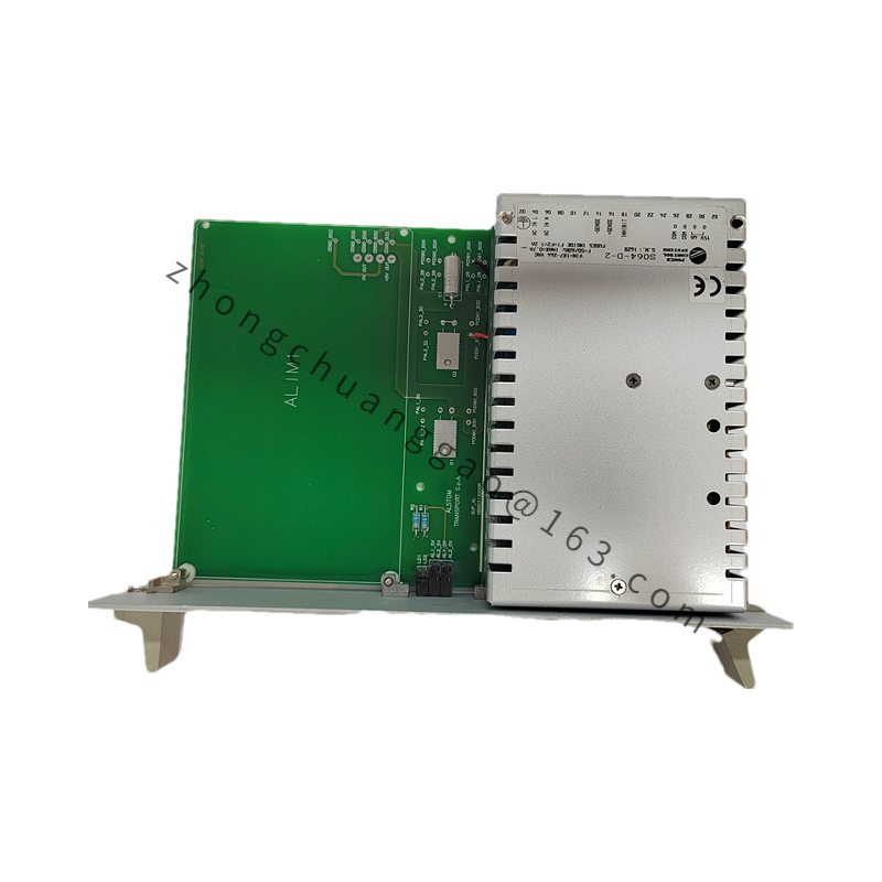
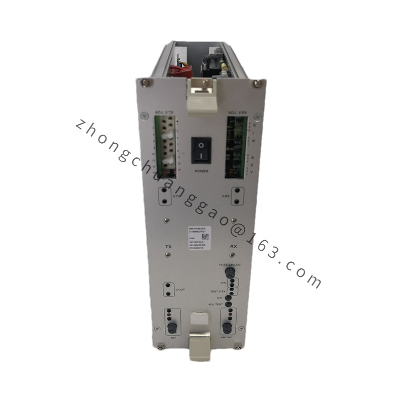
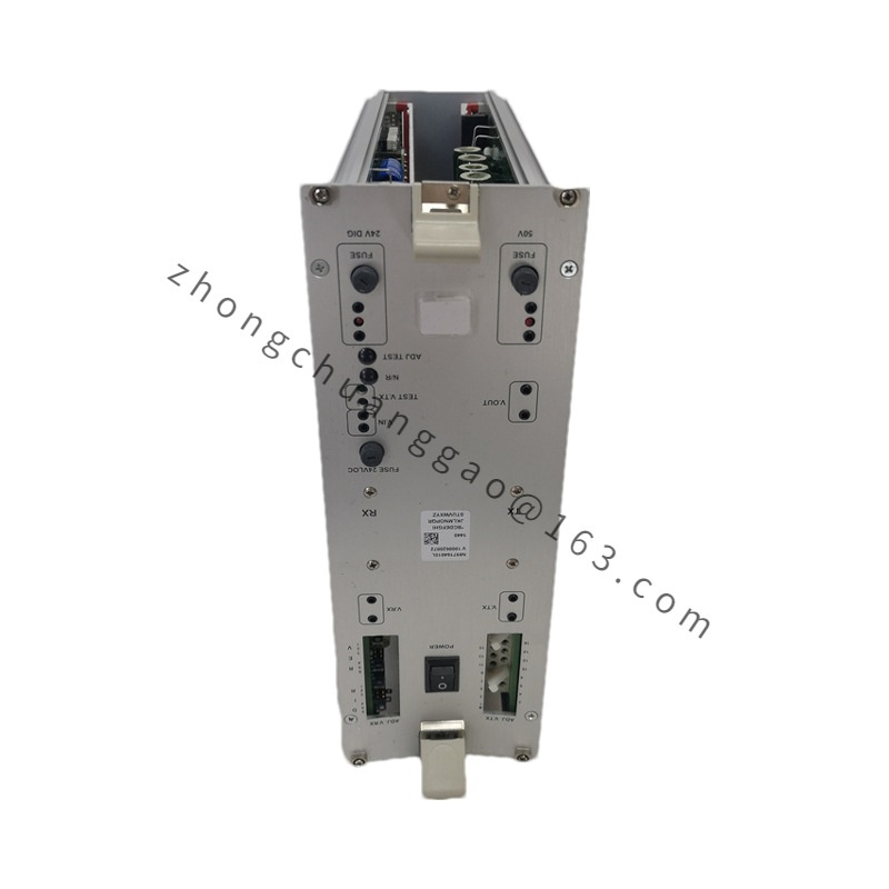
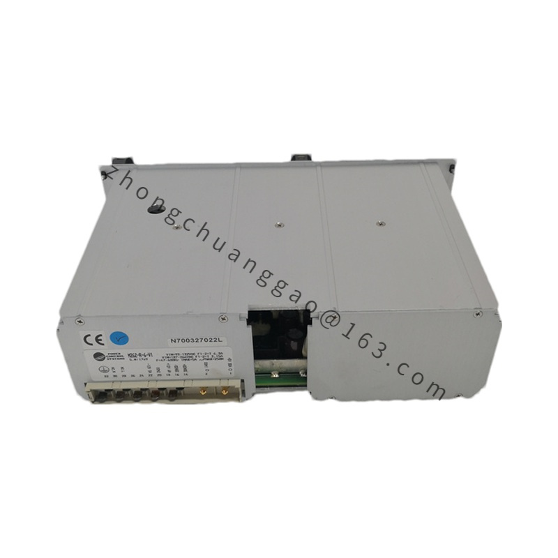
Form Factor: 6U-style rack card or plug-in control board according to the Microrec variant.
Functional Features
Synchronous sampling of generator voltage and current.
Real-time calculation of active power, reactive power, power factor and excitation demand.
Automatic voltage regulation with PID or manufacturer excitation algorithm.
Fault detection for overvoltage, overcurrent and signal loss.
Status LEDs and nonvolatile storage for calibration and event data.
Application Scenarios
Thermal power turbine-generator excitation panels.
Hydroelectric synchronous generator AVR systems.
Combined-cycle and gas-turbine generator voltage control.
Industrial generator sets and cogeneration plants.
Material and Structure
FR-4 printed circuit board with industrial conformal coating.
Steel or aluminum rack frame with anti-corrosion finish.
Gold-plated backplane connector and screw-type field terminals.
Isolation transformers or optocouplers for CT/VT input stages.
Working Principle
Generator PT and CT secondary signals enter isolated conditioning circuits, are scaled and filtered, then converted by the ADC. The controller computes voltage, current and excitation setpoints, compares them with references, and sends field-current commands to the power stage. Communication interfaces report data to DCS or SCADA.
Installation Requirements
Install in the designated Microrec rack with proper ventilation clearance.
Separate CT/PT wiring from high-voltage power cables.
Provide CT shorting terminals before maintenance.
Verify firmware and configuration match the generator rating before energization.
Usage Precautions
Never open CT secondary circuits while the generator is energized.
Calibrate voltage and current scaling after replacement.
Confirm excitation polarity and grounding scheme with the original system drawings.
Store spare cards in anti-static, dry and temperature-controlled conditions.