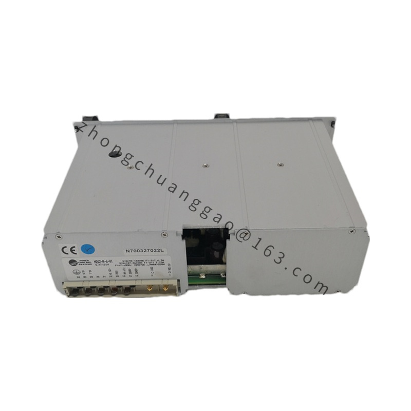
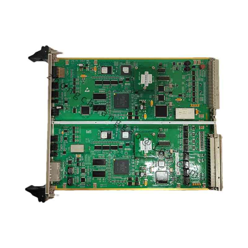
Technical Specifications: Frequency/speed version provides 3 independent inputs, sine 5 to 30 Vpp or TTL/CMOS square wave, 0.5 Hz to 5 kHz, approximately ±0.01% full-scale accuracy, 24 VDC backplane supply, around 3 W, channel-to-ground isolation 500 VAC, response below 1 ms, 0°C to +60°C industrial version. Flame version accepts UV, IR, visible or ion sensor signals, 24 VDC sensor supply, digital status and analog trend through backplane or RS-485 Modbus, self-diagnostics for flame loss and sensor fault, response up to 1 ms according to sensing type, IP20 module or higher protection in flame-amplifier enclosure. Combined EPSD/DFI versions provide 220 VAC input, isolated 24 VDC sensor output up to 500 mA, 0 to 10 V flame channels, RS-485 DFI bus, fault relay contacts 250 VAC 5 A, 168 mm x 92 mm x 32 mm, 0.42 kg, 0°C to +55°C.
Function Features: Adaptive gain for weak magnetic-pickup signals; galvanic isolation; flame-loss logic; self-diagnostic fault codes; hardwired relay interlock in flame-power versions.
Application Scenarios: Turbine overspeed protection and speed feedback; industrial burner management; boiler safety; gas-turbine flame monitoring.
Performance Parameters: Speed accuracy approximately ±0.01% in frequency mode; flame sampling response as low as 20 ms in combined power-supply versions; relay action below 50 ms on flame loss in defined configurations.
Material Composition: Flame-retardant FR4 PCB, PA66 indicator frame in combined versions, isolation transformer with epoxy filling, spring or screw copper-alloy terminals.
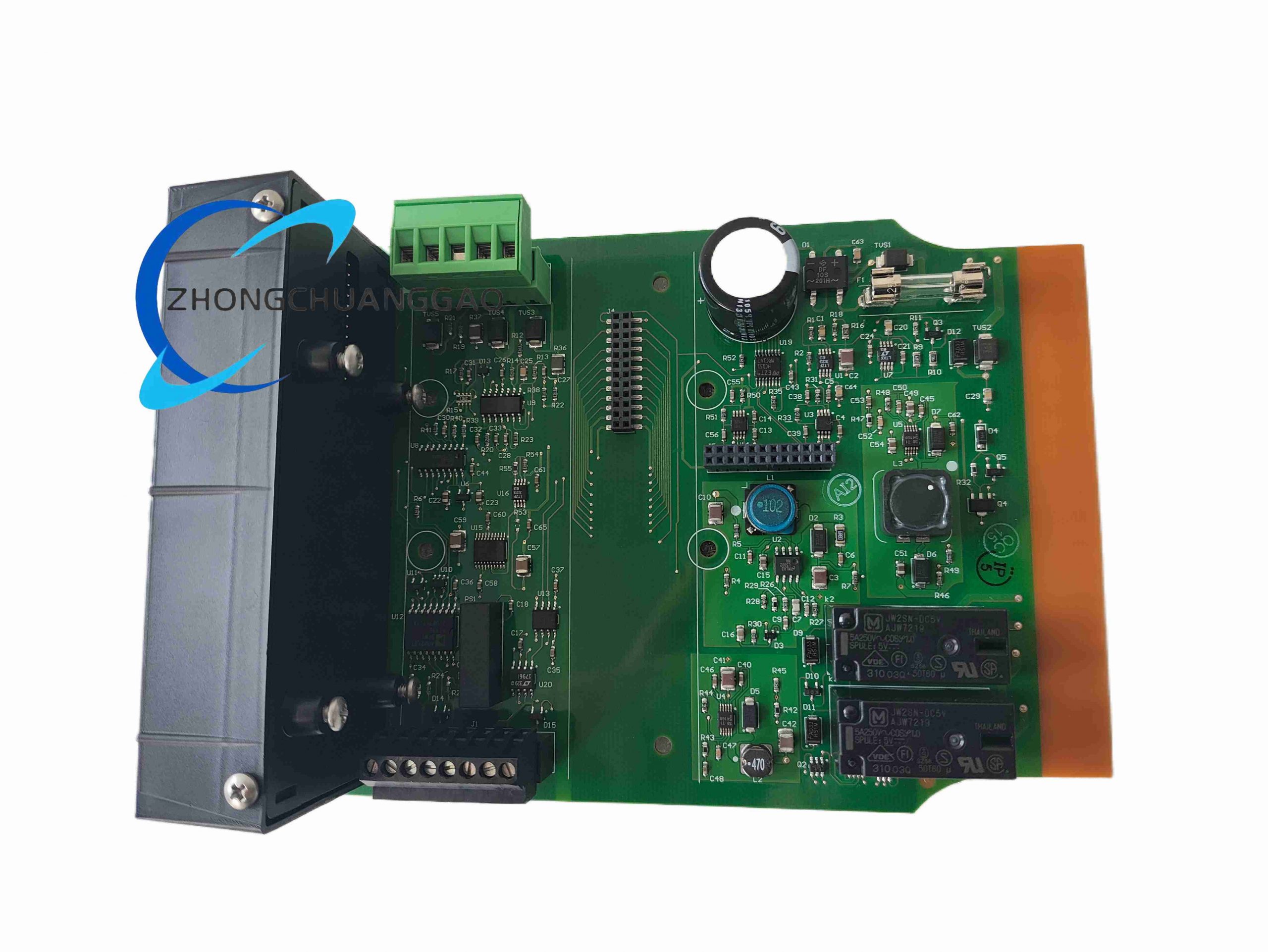
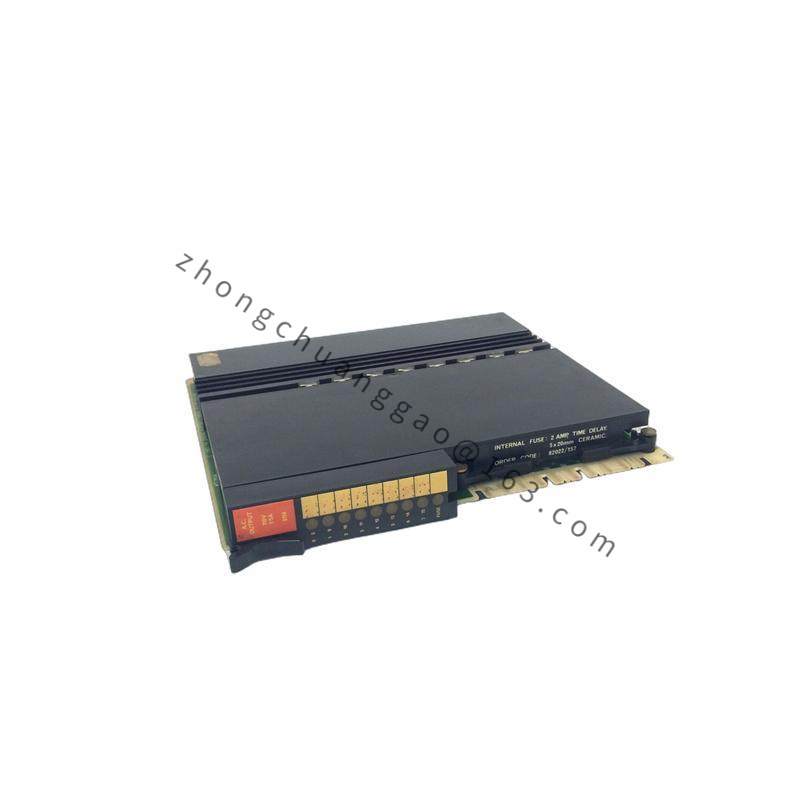
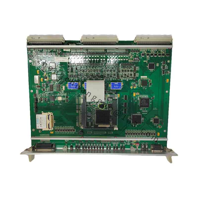
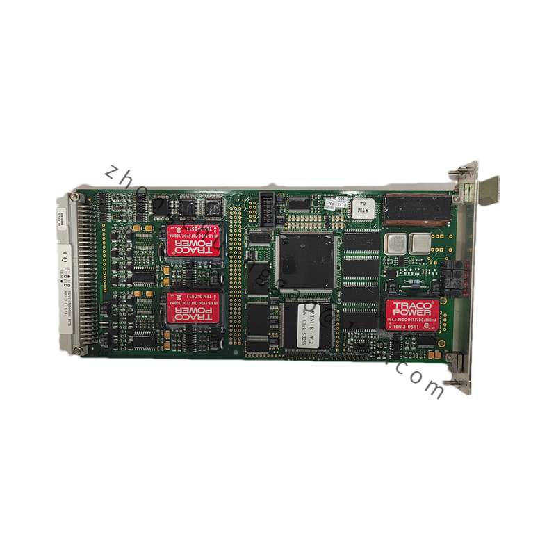
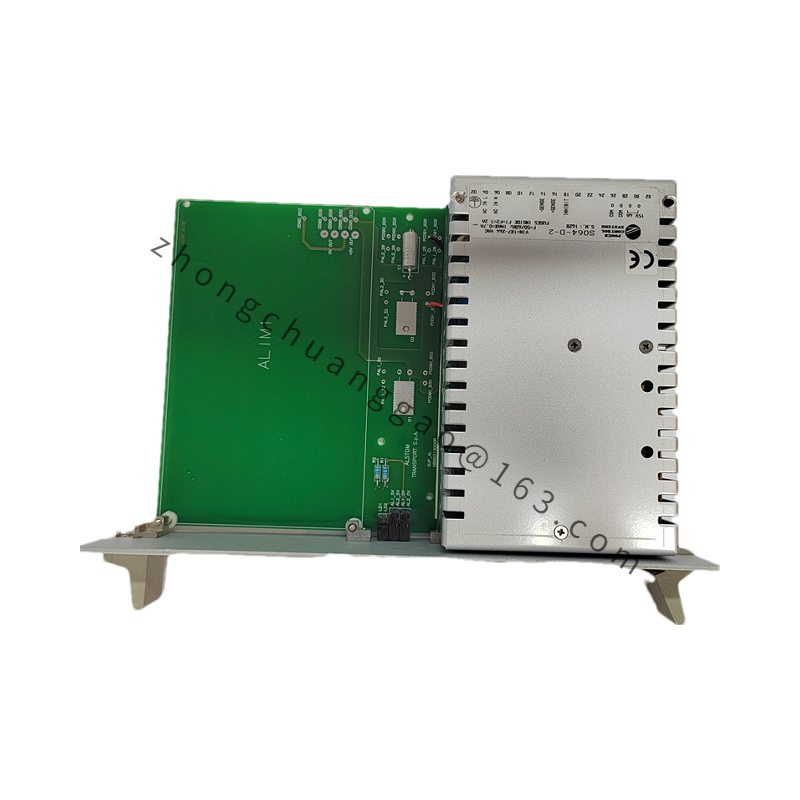
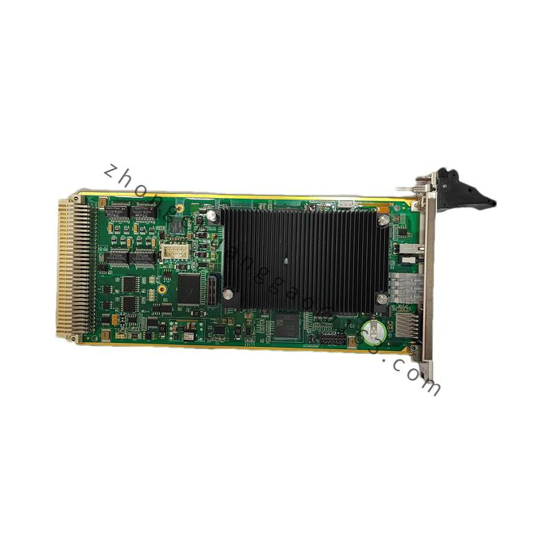
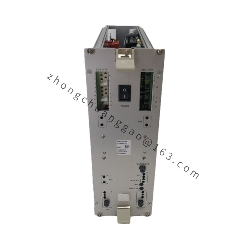
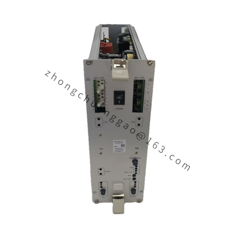
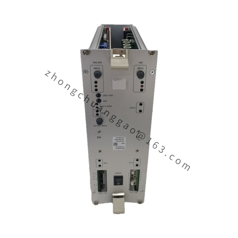
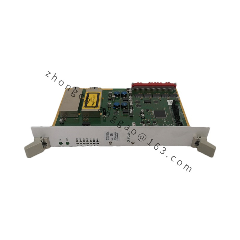
Structural Characteristics: Plug-in rack module for frequency versions; single-board DIN or cabinet unit for combined flame-power versions; front LEDs for power, flame, fault and relay; pluggable terminal blocks.
Working Principle: Magnetic pickup or pulse input is conditioned, counted and converted to speed values for turbine protection; flame sensor current or voltage is amplified, compared and encoded as flame-presence or fault data; the interface transmits states to the turbine or boiler controller through backplane, Modbus or relay outputs.
Installation Requirements: Use shielded twisted pair for magnetic pickup wiring with single-point grounding; set jumper or DIP for MPU, TTL or flame type; install in the specified Alstom TCS/I/O rack or flame cabinet; verify sensor supply rating before connecting UV/IR/ion detectors.
Usage Precautions: Do not exceed maximum input voltage on frequency channels; verify jumper settings before energizing; test flame-loss simulation and relay interlock during commissioning; keep sensor cables separated from power conductors.