Technical Specifications
Compatible relay frame: 193-EC_E family
Relay adjustment range: 18–90 A
Compatible relay bodies: 193-EC1 through EC5
Compatible contactors: Bulletin 100-C sizes C60, C65, C70, C75, C80 and C85
NEMA compatibility: Bulletin 500 Size 4 through 592-EC_E
Maximum operational voltage: 600 VAC (UL)
Rated insulation voltage: 690 VAC, 50/60 Hz
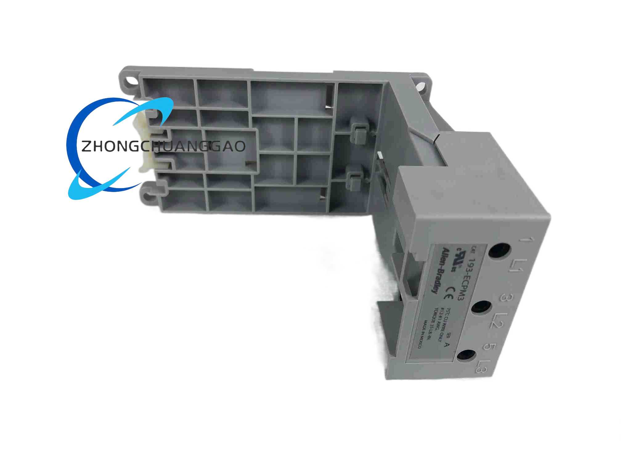
Power-terminal wire range: single conductor 12–1 AWG (4–35 mm²); multiple conductor 6–2 AWG (4–25 mm²)
Power-terminal torque: 35 lb-in (4 N·m)
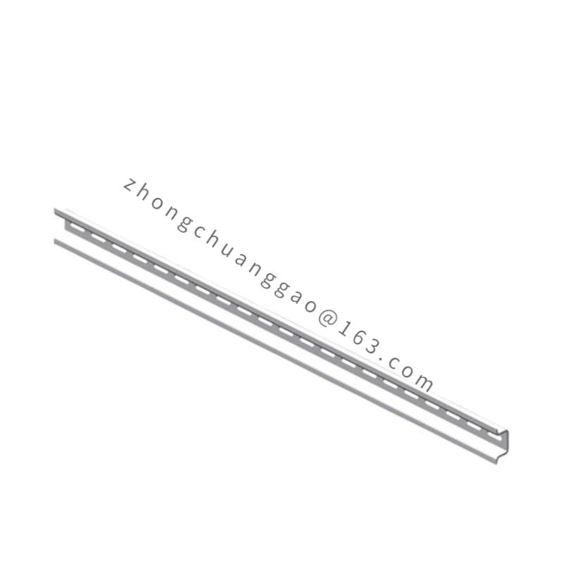
Mounting methods: panel mount through cut-out; 35 mm top-hat DIN rail to EN 50022-35
Housing material: flame-retardant engineering thermoplastic, UL 94 V-0
Dimensions: 71.7 mm wide × 150.5 mm high × 60 mm deep; approximately 155 mm high with a 193-EIMD module stacked
Weight: approximately 0.21 kg (0.46 lb)
Operating temperature: -20 °C to +60 °C
Certifications: UL 508, CSA, CE, CCC and RCM as part of a listed assembly
Country of origin: Mexico
UPC: 611320526110
Functional Features
Decouples overload-relay location from contactor location
Supports both panel-mount and DIN-rail mounting
Maintains alignment with the contactor trip actuator for correct trip and reset operation
Carries line-side and load-side power conductor terminals
Preserves the relay’s protection behaviour when remotely mounted
Material Composition
Housing: UL 94 V-0 flame-retardant engineering thermoplastic
Hardware: steel mounting and alignment hardware
Power terminals: copper alloy conducting elements
Structural Features
Precision alignment features for secure relay seating
Cut-out panel-mount provision
35 mm DIN-rail snap-mount provision
Power-conductor terminal positions for line and load connections
Working Principle
The adapter forms a fixed mechanical platform and conducts main power between its line-side and load-side terminals. The overload relay clips or mounts into the adapter, while the adapter aligns the relay’s trip mechanism with the contactor. Trip and reset actions therefore operate as they would in a direct-mounted starter.
Application Scenarios
Motor control centre doors where relay displays and controls must remain accessible
Remote mounting of E3/E3 Plus relays away from the contactor
Panels requiring door-mounted motor protection access without opening the energised compartment
Retrofit and maintenance of installed E3 Plus bases
Installation Requirements
Mount by panel cut-out screws or by snapping onto a standard 35 mm top-hat DIN rail
Use a compatible 193-EC relay body and Bulletin 100-C contactor in the listed size range
Torque power terminals to 35 lb-in (4 N·m)
Check line-side and load-side terminal alignment with the relay frame
Confirm trip-actuator alignment with the contactor before energising
Usage Notes
This is an adapter, not an overload relay or protection device
The current and voltage capability are governed by the mounted relay and the assembly rating
Discontinued on 31 October 2019
Functional alternatives for E300/E200 users include 193-ESM-I-100A-E3T and 193-ESM-VIG-100A-E3T