Technical Specifications
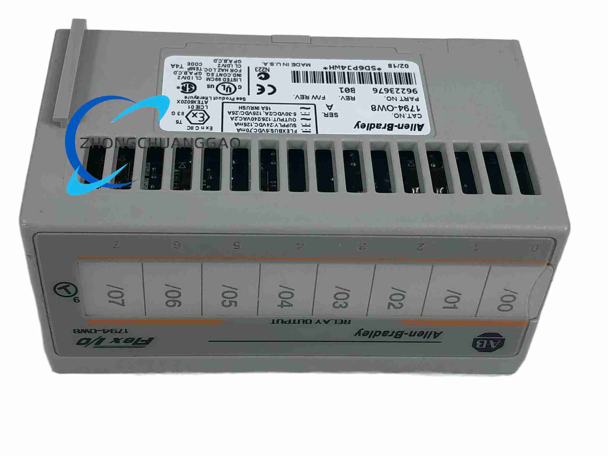
Output points: 8 isolated relay outputs
Relay type: Electromechanical, Form A, normally open
Backplane current draw: 35 mA at 5 VDC
Module supply: 24 VDC, 125 mA
Performance Parameters
Resistive DC rating: 2 A at 5–30 VDC; 0.5 A at 48 VDC; 0.25 A at 125 VDC
Resistive AC rating: 2 A at 125 VAC and 240VAC
Inductive load (L/R 7 ms): 2 A steady state at 5–30 VDC; 0.5 A at 48 VDC; 0.25 A at 125 VDC
AC inductive make rating: 15 A at 125VAC and 240VAC, power factor 0.4
AC inductive steady-state rating: 2 A
Make VA: up to 1800 VA; break VA: 180 VA
Switching frequency limit: 1 operation every 3 seconds at rated load (0.3 Hz maximum)
Contact initial resistance: 30 mΩ
Typical contact bounce: 1.2 ms
Expected electrical contact life: minimum 100,000 operations at rated load
Isolation Ratings
Relay-to-relay isolation: 250 V continuous, basic insulation
Relay-to-backplane isolation: 250 V continuous, basic insulation
Power-to-backplane isolation: 50 V continuous, basic insulation
Material Composition
Contact material: silver alloy electromechanical relay contacts
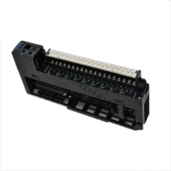
Housing: moulded thermoplastic module body with integral terminal-base interface
Structural Features
Independent relay circuits with no common supply rail across the eight outputs
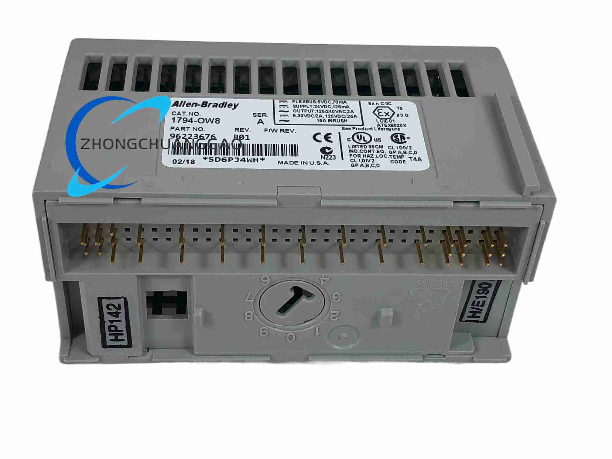
DIN-rail mounted FLEX I/O terminal base architecture
Removable terminal base for wiring retention during module replacement
Front-facing status indication per output point
Working Principle
A logic command from the FLEX I/O adapter energises the selected internal relay coil. The closed electromechanical contact then completes the external field-circuit path. Because the contact path is mechanically isolated from the backplane, each output can carry a separate AC or DC supply without a common return.
Application Scenarios
Switching contactor and relay coil loads within the published contact ratings
Mixed-voltage panels where each output drives an independent supply
Low-frequency actuator and solenoid control
FLEX I/O installations requiring genuine isolated contacts rather than transistor outputs
Installation Requirements
Confirm compatibility with an approved FLEX I/O terminal base (TB2, TB3, TB3S, TBN or TBNF option)
Torque field wiring to the terminal base specification
Identify and document every external AC and DC supply feeding the isolated contacts
Verify the selected terminal base supports the applied voltage and wire size
Usage Notes
The 2 A headline rating applies only to the published resistive voltage conditions and is not a universal rating
Apply load-specific current limits; inductive loads must use approved suppression
Switching faster than 0.3 Hz will accelerate contact wear and may exceed mechanical duty
Excessive steady current, inrush, inductive energy, failed suppression or inadequate fusing can weld a contact closed
De-energising the FLEXBus does not prove that every field circuit is de-energised; prove all hazardous circuits dead before removing the module
Keep isolated circuits physically and electrically separated in accordance with the installation drawings
Status: Active Mature. Rockwell Automation lists an estimated five-day lead time and a one-year standard warranty.