Digital guide

You are here:

AEG S74D-PB0-F0V0

Product Introduction:
The AEG S74D-PB0-F0V0 is a programmable electronic motor protection relay from the S74D series, configured with phase monitoring (PB0) and overvoltage protection (F0V0) as primary functions. It is designed for critical three-phase motor applications where phase sequence and voltage stability are paramount.

Detailed content

Model Series: S74D Series (Motor Protection Relays)

Technical Specifications:

  • Rated Current (In): 1 A to 10 A (selectable via DIP switches)
  • Voltage Range: 100V AC to 690V AC (3-phase)
  • Phase Monitoring (PB0): Phase failure, phase reversal, phase unbalance (>15%)
  • Overvoltage Setting (F0V0): 400V to 500V (adjustable, default 440V)
  • Undervoltage Setting: Disabled (PB0 configuration)
  • Frequency Range: 45 Hz to 65 Hz
  • Output Contacts: 2 × Changeover Relay (8A / 250V AC) + 1 × Alarm Contact (NO, 5A)
  • Accuracy: ±1% of setting value
  • Response Time: <30 ms (phase failure) / <100 ms (overvoltage)
  • Operating Temperature: -25°C to +60°C
  • Protection RatingIP20 (front panel: IP40 with cover)
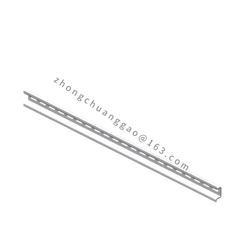
  • MountingDIN rail 35 mm (EN 60715)
  • Power Supply: 100–240V AC/DC (auxiliary supply)
  • Dimensions: 90 mm × 70 mm × 62 mm
  • Weight: 280 g
  • Standards Compliance: IEC 60255-1, IEC 60947-6-2, UL 508, CSA C22.2

Functional Features:

  • Phase failure detection — trips within 30 ms if any phase is lost
  • Phase reversal detection — trips if L1/L2/L3 sequence is incorrect
  • Phase unbalance protection — trips if voltage unbalance exceeds 15%
  • Overvoltage protection (F0V0) — trips if voltage exceeds 440V (adjustable)
  • Start-up delay (adjustable 0–30 s) to allow inrush current decay
  • Curtain timer — adjustable delay before re-energization after fault (0–600 s)
  • LED status indicators: Power (green), Run (green), Fault (red), Alarm (yellow)
  • Test button — simulates fault condition for relay verification

Structural Characteristics:

  • Modular DIN rail housing (90 mm width)
  • Front cover with hinged transparent window
  • Screw terminal blocks for all power, voltage sense, and output connections
  • DIP switch array (8 switches) on front for full parameter configuration
  • LCD display option (on higher variants) — not present on PB0 base model

Working Principle:
Three-phase voltages are sampled via resistive voltage dividers at 4 kHz sampling rate. The 16-bit MCU performs FFT analysis to detect phase sequence, calculate RMS values, and measure phase-to-phase unbalance. The phase failure algorithm uses a voltage threshold + time-delay logic (30 ms). The overvoltage function (F0V0) compares RMS voltage against the setpoint with a 100 ms time delay to avoid nuisance trips from transient spikes. Upon fault detection, the output relay de-energizes, opening the motor contactor circuit.

Advantages & Highlights:

  • Phase reversal protection — prevents motor damage from incorrect wiring (critical for new installations)
  • 30 ms phase failure response — faster than most electromechanical relays
  • No external CTs required — direct voltage sensing eliminates current transformer costs
  • DIP-switch configuration — fully operational without PC software
  • Test button enables commissioning verification without creating actual fault

Applicable Industries:

  • Critical process motors (pumps, compressors) where phase loss causes catastrophic damage
  • Generator feed protection
  • UPS output monitoring
  • Marine and offshore motor protection
  • Data center cooling systems

Installation Requirements:

  • Mount on DIN rail TS35 with minimum 30 mm spacing between adjacent devices
  • Connect L1, L2, L3 to voltage sensing terminals (do not connect neutral)
  • Wire output changeover contacts in series with motor contactor coil (A1–A2)
  • Provide dedicated auxiliary supply (100–240V AC/DC) — do not derive from motor supply
  • Use shielded cable for voltage sense leads in high-EMI environments

Usage Precautions:

  • Verify phase sequence before energizing — PB0 will trip on reversal
  • Set overvoltage threshold 5% below motor nameplate voltage rating
  • Set phase unbalance threshold at 15% (do not go below 10% — causes nuisance trips)
  • Perform relay test via test button monthly as per maintenance schedule
  • After fault trip, use curtain timer delay before restart — do not manually bypass
  • Do not modify DIP switches while relay is energized — power down first

You may also like