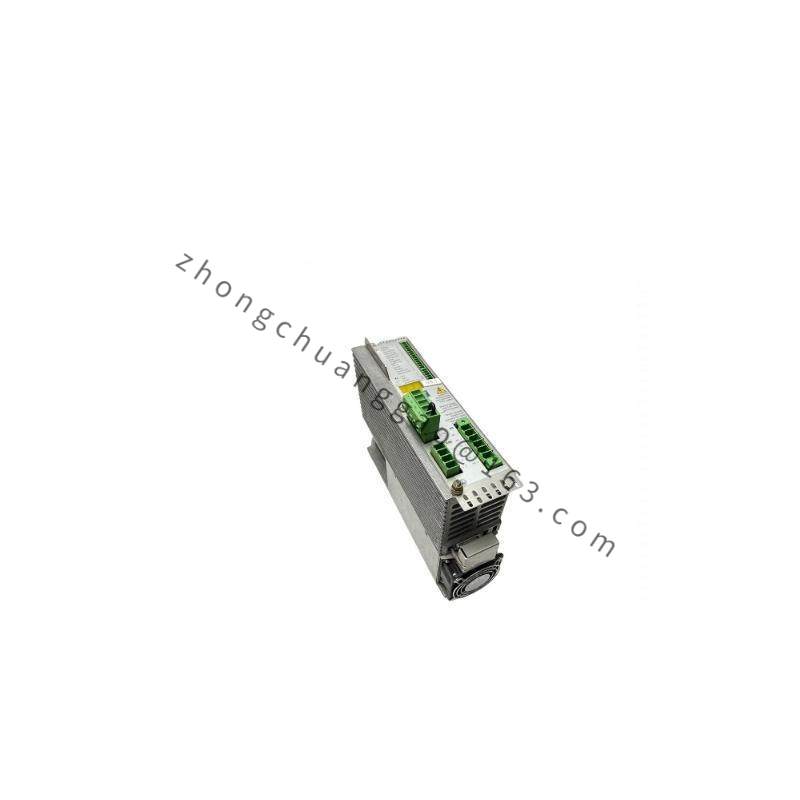
AEG KP1-C05 SEAB
Product Category: Electromagnetic Contactor / Control Relay
Product Introduction:
The AEG KP1-C05 SEAB is a compact electromagnetic contactor (relay) from the KP1 series, rated at 5A with a 24V DC coil. The SEAB suffix indicates compliance with the SEAB (Society of Environmental Engineers) certification for use in specific environmental and safety-critical applications. It is used for switching control circuits in HVAC, industrial automation, and building management systems.
Detailed content
Technical Specifications:
- Model: KP1-C05
- Series: KP1
- Coil Voltage: 24V DC
- Rated Current (AC-1): 5A at 230V AC
- Rated Current (DC-1): 5A at 220V DC
- Number of Poles: 1 NO + 1 NC (SPDT — Single Pole Double Throw)
- Coil Power Consumption: 0.5W (hold) / 2.0W (pull-in)
- Contact Material: AgSnO₂ (Silver Tin Oxide)
- Mechanical Life: 10,000,000 operations
- Electrical Life (AC-1): 500,000 operations at 5A, 230V AC
- Operating Time: Pull-in: ≤ 15 ms / Drop-out: ≤ 10 ms
- Insulation Resistance: ≥ 100 MΩ at 500V DC
- Dielectric Strength: 2500V AC, 1 min (between coil and contacts)
- Protection Class: IP20 (when mounted in control panel)
- Operating Temperature: -25°C to +70°C
- Mounting: DIN rail 35 mm (EN 60715) or screw mounting
- Standards: EN 60947-4-1, EN 60947-5-1, IEC 61813
- SEAB Certification: Yes — certified for environmental control applications
Functional Features:
- SPDT configuration (1NO + 1NC): Allows simultaneous switching of two circuits.
- AgSnO₂ contacts: Superior arc suppression and welding resistance compared to AgNi or AgCdO.
- LED status indicator: Visual confirmation of coil energization (on selected variants).
- Snubber circuit (RC network): Integrated across contacts to suppress voltage transients on inductive loads.
- Coil suppression diode: Built-in flyback diode for DC coil protection.
- Mechanical indicator: Flag shows contact position (energized/de-energized).
Material Composition:
- Coil Bobbin: PA66 GF30 (glass-fiber reinforced polyamide)
- Coil Wire: Copper, Class H insulation (180°C)
- Contact Plates: CuZn37 brass, silver-plated
- Contact Tips: AgSnO₂ (88% Ag, 12% SnO₂) sintered
- Armature: Soft iron (low carbon steel), nickel-plated
- Housing: PA66 GF30, UL94 V-0 flame-retardant, self-extinguishing
- Terminals: Screw terminals, 3.5 mm² max wire capacity, tin-plated brass
Structural Features:
- Compact modular design: Width 17.5 mm per module on DIN rail.
- Clip-on DIN rail mounting with snap-in mechanism.
- Clear contact status flag visible from the front.
- Terminal labeling: A1, A2 (coil); 11, 12, 14 (contacts: NC, COM, NO).
Working Principle:
When 24V DC is applied to the coil terminals (A1/A2), current flows through the copper winding, generating a magnetic field that pulls the soft iron armature toward the core. This mechanical movement closes the NO contact (11–14) and opens the NC contact (11–12). When the coil is de-energized, a return spring pushes the armature back to its resting position, reversing the contact states. The flyback diode across the coil absorbs the inductive voltage spike during de-energization, protecting the driving circuit. The RC snubber across the contacts suppresses arcing during switching of inductive loads.
Advantages & Highlights:
- AgSnO₂ contacts provide 500,000 cycle electrical life at rated load.
- 15 ms pull-in time enables fast switching for automation sequences.
- SEAB certified — verified for environmental and safety-critical installations.
- Compact 17.5 mm width saves space in control panels.
- 24V DC coil is standard for building automation and safety circuits.
Applicable Industries / Use Cases:
- HVAC control systems
- Building automation (BMS/BAS)
- Industrial control panels
- Safety circuits (fire alarm, emergency stop)
- Lighting control systems
Installation Requirements:
- Mount on DIN rail EN 60715 (35 mm) in a control cabinet.
- Connect coil to 24V DC control supply (A1 = +24V, A2 = 0V).
- Connect load circuits to 11 (COM), 12 (NC), 14 (NO) terminals.
- Use wire size 0.5–2.5 mm² for coil; 0.5–4 mm² for contacts.
- Ensure ambient temperature does not exceed +70°C in the cabinet.
- Provide adequate ventilation — derate by 10% per 10°C above 40°C.
Usage Precautions:
- Do not exceed rated current of 5A — overcurrent will weld contacts.
- Use the correct coil voltage (24V DC) — applying 230V AC to the coil will destroy it instantly.
- For inductive loads (motors, solenoids), always use the variant with RC snubber or add an external suppressor.
- Replace if contact resistance exceeds 50 mΩ (measured with micro-ohmmeter).
- Store in dry conditions; the coil insulation can degrade in high humidity.
.jpg)