.jpg "PC-0984-685 AS-9715-001(1)")
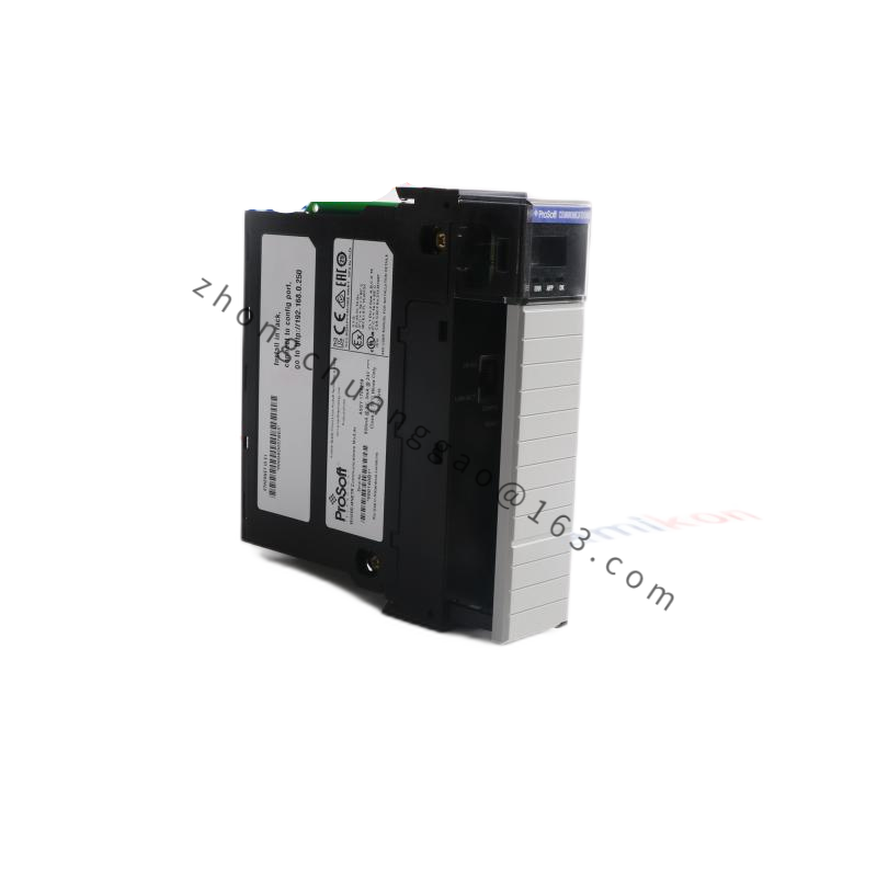
AEG D984-385 984 385D
Product Introduction:
The AEG D984-385 (also referenced as 984 385D) is a numerical protective relay designed for overcurrent and earth fault protection of electrical circuits, motors, transformers, and feeders in industrial power distribution systems. It provides precise, adjustable protection functions with multiple characteristic curves, communication capability, and event recording. This relay is a direct replacement for legacy electromechanical overcurrent relays and offers significantly enhanced accuracy, flexibility, and diagnostics.
Detailed content
Technical Specifications:
- Model Designation: D984-385 / 984 385D
- Relay Type: Numerical overcurrent and earth fault protective relay
- Number of Protection Functions: 3 overcurrent stages + 1 earth fault stage (configurable)
- Current Input Range: 0.1A to 10A (via CT), 1A to 100A (direct — selectable)
- Rated Frequency: 50 Hz / 60 Hz
- Operating Current Range: 0.1 × In to 20 × In (adjustable in 0.01A steps)
- Time Dial Setting (TDS): 0.01 to 1.50 (in 0.01 steps)
- Characteristic Curves: Standard Inverse (SI), Very Inverse (VI), Extremely Inverse (EI), Long-Time Inverse (LTI) — IEC 60255
- Operating Time: 0.02 s to 30 s (dependent on curve and setting)
- Accuracy: ±2.5% at 1.2 × In (overcurrent), ±3% at 1.2 × In (earth fault)
- Number of Output Contacts: 3 changeover contacts (CO) + 1 tripping contact (NO)
- Contact Rating: 5A at 250V AC (resistive), 2A at 250V DC
- Communication Interface: RS-485 (Modbus RTU)
- Power Supply: 85V to 264V AC/DC (universal)
- Power Consumption: 4 VA (AC), 3 W (DC)
- Operating Temperature: -10°C to +55°C
- Storage Temperature: -25°C to +70°C
- Dimensions (W x H x D): 112 mm x 120 mm x 80 mm (approximate, panel-mount)
- Weight: Approximately 0.9 kg
- Mounting: Panel mount (clip-on DIN rail or screw mounting)
- Standards Compliance: IEC 60255-1, IEC 60255-4, IEC 60255-5, IEC 61000-4-2, IEC 61000-4-3, IEC 61000-4-4, IEC 61000-4-5
Functional Features:
- 4 Protection Stages:
- Stage 1: Overcurrent — definite time or inverse time
- Stage 2: Overcurrent — definite time or inverse time
- Stage 3: Overcurrent — definite time (backup protection)
- Stage 4: Earth fault — definite time or inverse time
- Automatic Reclose: 1-shot or multi-shot reclose (up to 4 attempts)
- Event Recording: 64 disturbance records with timestamps (1 ms resolution)
- LED Indicators: Power (green), Trip (red), Alarm (amber), Stage Active (x4)
- Front Panel: 4-digit LED display for current, settings, and events
- Password Protection: 3-level access (viewer, engineer, administrator)
- Self-Supervision: Continuous monitoring of CT circuit, power supply, and internal hardware
Performance Parameters:
- Trip Time Accuracy: ±1% at 5 × In (overcurrent), ±2% at 5 × In (earth fault)
- Reset Ratio: 0.95 to 0.99 (adjustable)
- Burden: < 0.5 VA at rated current
- Isolation: 2500V DC between current input and contact output (1 minute)
- EMC Immunity: IEC 61000-4-2: 8 kV ESD, IEC 61000-4-3: 10 V/m RF, IEC 61000-4-4: 4 kV EFT, IEC 61000-4-5: 2 kV surge
- MTBF: > 50,000 hours (calculated)
Material Composition:
- Housing: Polycarbonate (UL94 V-0) front panel + ABS rear cover
- PCB: FR-4 double-sided with conformal coating
- Current Input: Dedicated CT input terminals (5A / 1A selectable via DIP switch)
- Contacts: Silver-cadmium oxide (AgCdO) for high reliability
- Terminals: Screw terminals (4 mm² max wire)
- Display: 7-segment LED (red) with diffuser
Structural Features:
- Front-panel mount design (clip-on DIN rail compatible)
- 4-digit red LED display for real-time current and setting values
- 4 stage-active LEDs (green) + Trip LED (red) + Alarm LED (amber)
- 3 changeover contact terminals + 1 NO trip contact terminal
- RS-485 communication terminal block
- CT input terminals (In, Is) with polarity marking
- Removable front cover for wiring access
Working Principle:
The D984-385 continuously samples the current input via its internal ADC (16-bit, sampling rate 4 kHz). The sampled current is compared against the configured pickup setting (Stage 1–4). When the measured current exceeds the pickup threshold, the relay’s processor calculates the operating time based on the selected IEC inverse time characteristic curve (SI, VI, EI, LTI) and the configured Time Dial Setting (TDS). If the calculated time elapses, the relay trips the output contact, opening the circuit breaker. The earth fault stage uses a residual current measurement (vector sum of 3-phase currents) for ground fault detection. All events (trip, alarm, current values, setting changes) are recorded in non-volatile memory with 1 ms timestamps.
Advantages & Highlights:
- IEC 60255 Compliant: All standard inverse curves (SI, VI, EI, LTI)
- 4 Independent Stages: Overcurrent (3) + Earth fault (1) with full configurability
- Universal Power Supply: 85V–264V AC/DC — works worldwide
- Event Recording: 64 disturbance records with 1 ms resolution for post-fault analysis
- Replace Electromechanical Relays: Direct drop-in replacement for legacy overcurrent relays
- Self-Monitoring: CT supervision, power supervision, hardware diagnostics
Applicable Industries:
- Industrial power distribution (MCC, switchgear)
- Motor protection (pumps, compressors, fans, conveyors)
- Transformer protection (feeder and backup)
- Generator protection
- Mining and heavy industry
- Commercial building electrical systems
- Renewable energy (wind turbine, solar inverter protection)
Installation Requirements:
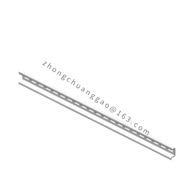
- Mount on DIN rail (35 mm) or screw to panel
- Connect CT secondary leads to In/Is terminals (observe polarity: P1→In, P2→Is)
- Connect trip output to circuit breaker trip coil (NO contact)
- Connect alarm output to SCADA/BMS system (changeover contact)
- RS-485 connection: A+, B− to Modbus network (max 32 devices per segment, 120 Ω terminator)
- Power supply: 85V–264V AC/DC connected to L, N terminals
- Ensure CT ratio matches relay setting (e.g., 200/5A CT with relay set to 100% = 100A primary)
Usage Precautions:
- Always verify CT polarity before energizing — reversed CT will cause maloperation
- Do not exceed 10A continuous current input (use CT for higher currents)
- Set pickup current above maximum load current to avoid nuisance tripping
- Test trip function after installation and after any setting change
- Keep front panel clean — dust on LED display reduces visibility
- Do not open relay housing — all adjustments via front panel or software
- Replace relay after 15 years or if self-test fails