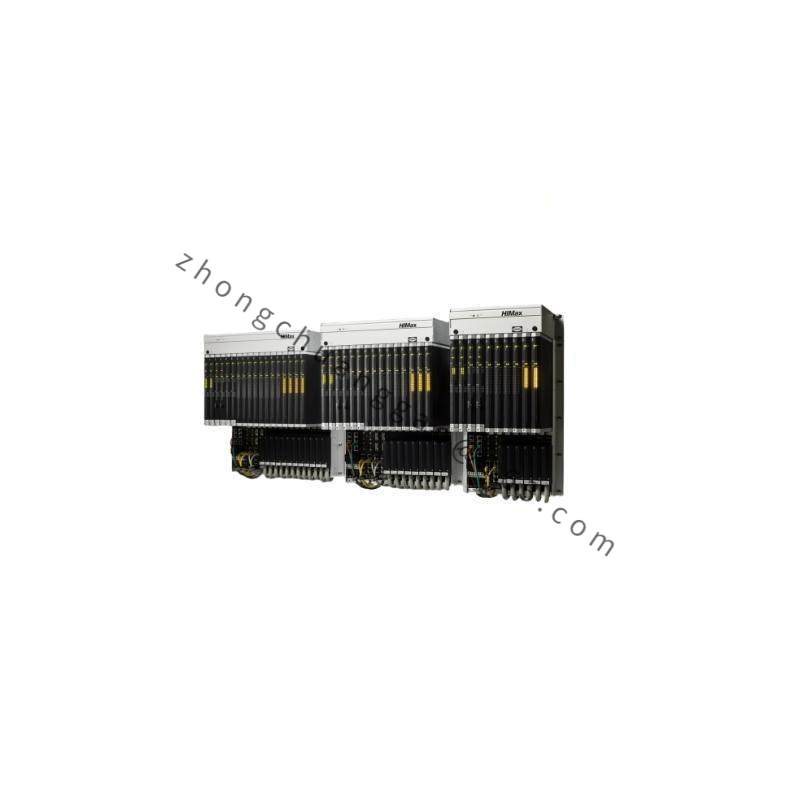

Product Introduction:
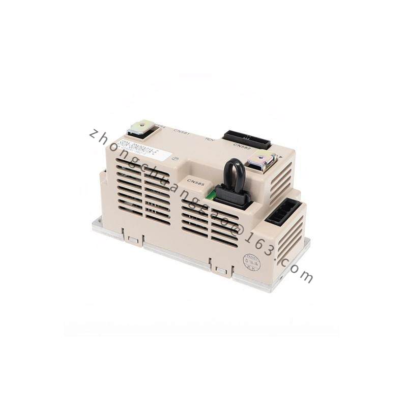
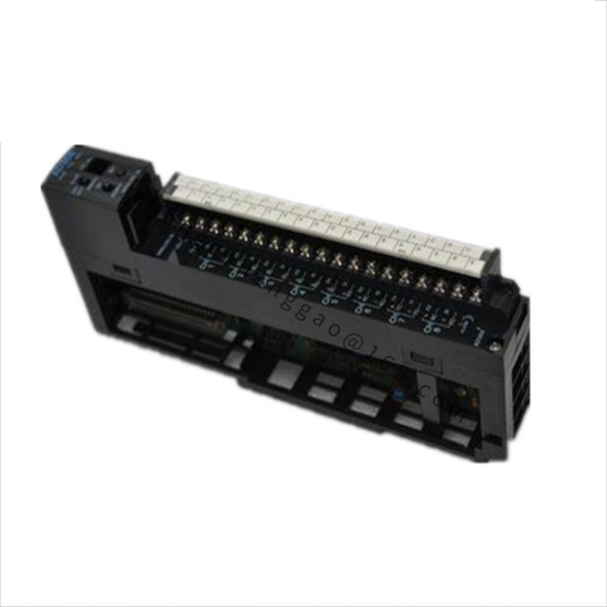
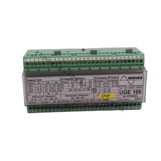
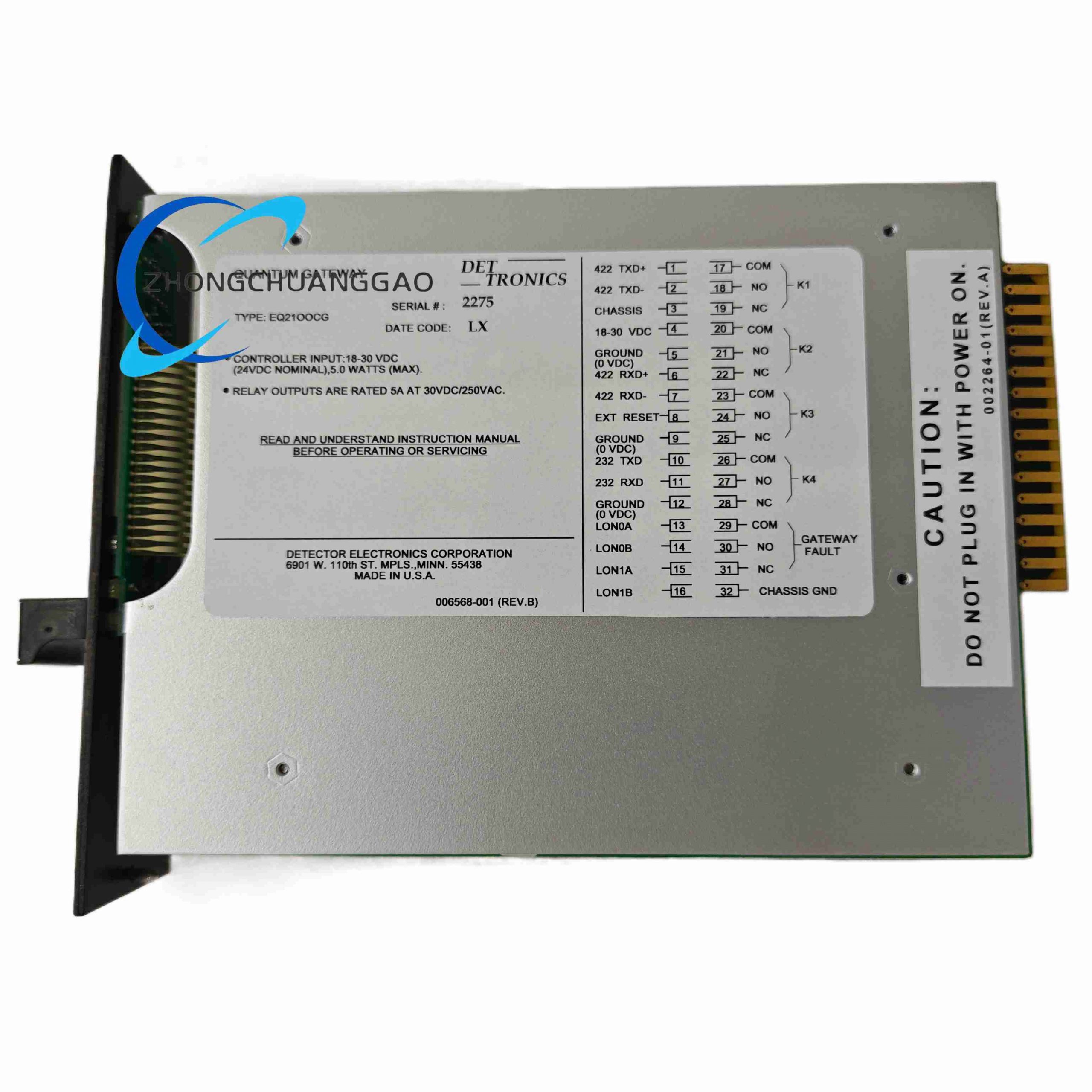
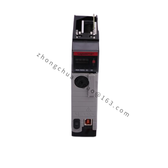
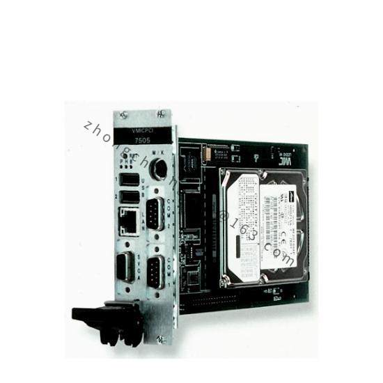
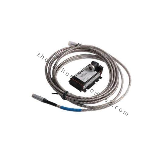
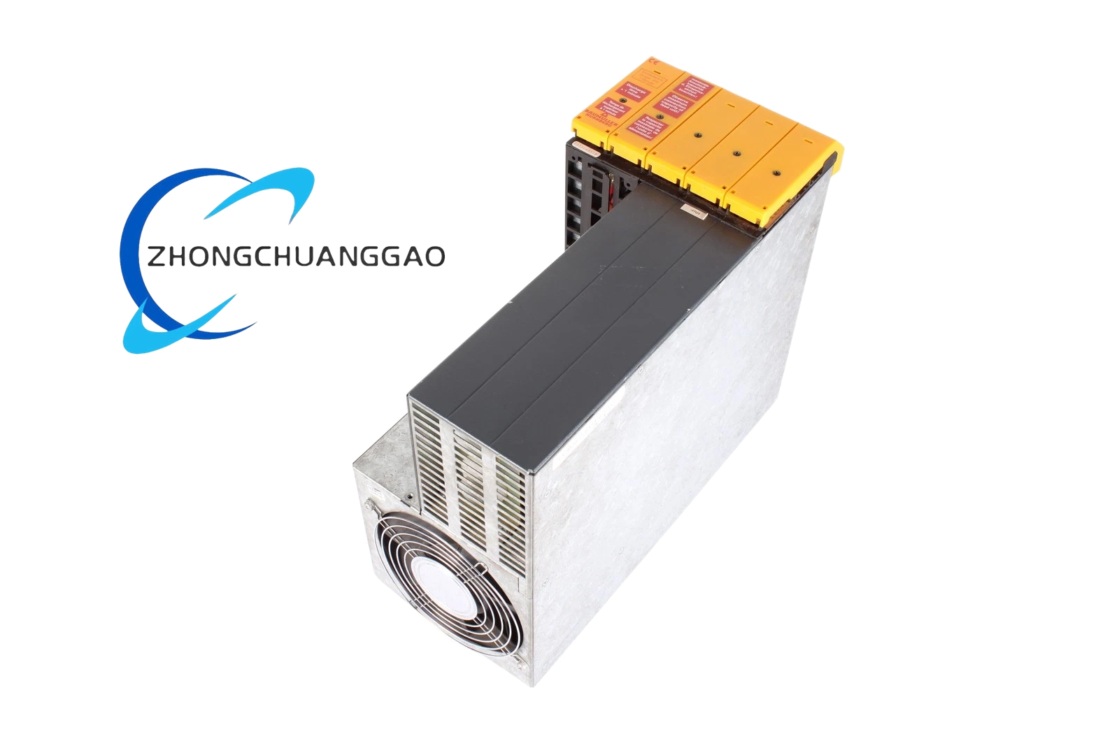
The AEG AS-B875-011 is a current transducer/sensor from the AS-B875 product family. It is designed to measure AC or DC current in industrial power systems and provide a proportional output signal (typically 4–20 mA or 0–10 V) for monitoring, metering, and control applications. The “011” suffix denotes the specific output range/calibration variant.
Technical Specifications:
| Parameter | Value |
|---|---|
| Model | AS-B875-011 |
| Measured Quantity | AC/DC Current |
| Primary Current Range | 0–500 A AC (typical for B875 variant) |
| Secondary Output | 4–20 mA DC (2-wire) or 0–10 V DC |
| Rated Primary Current (Ipn) | 500 A |
| Accuracy Class | Class 0.5 (±0.5% of reading) |
| Frequency Range | 45–65 Hz (AC), DC to 1 kHz |
| Supply Voltage | 24 V DC (2-wire) / 24–240 V AC/DC (3-wire) |
| Burden Resistor | 250 Ω (for 4–20 mA output) |
| Insulation Voltage | 2.5 kV AC (primary to secondary) |
| Standards Compliance | IEC 61869-2, EN 61869-2, UL 508 |
| Degree of Protection | IP20 (front), IP54 (with cover) |
| Ambient Temperature | -25°C to +60°C (operating), -40°C to +85°C (storage) |
| Mounting | DIN 35 mm rail or panel mount (M3 screws) |
| Response Time | < 100 ms (90% of final value) |
| Linearity Error | < 0.2% of full scale |
Material Composition:
Structural Features:
Working Principle:
The current sensor operates on the electromagnetic induction principle. The primary conductor (busbar or cable) passes through the toroidal core. The alternating current in the primary conductor generates a magnetic flux in the core, which induces a proportional current in the secondary winding. The signal conditioning circuit converts this current into a standardized 4–20 mA DC output (or 0–10 V) that is linearly proportional to the primary current. For DC measurement, a Hall-effect sensor is used instead of the current transformer principle. The output is galvanically isolated from the primary circuit, providing safe measurement even at high primary voltages.
Functional Features:
Performance Parameters:
| Parameter | Value |
|---|---|
| Accuracy (Class 0.5) | ±0.5% at 100% Ipn |
| Accuracy at 10% Ipn | ±0.75% |
| Phase Error | < 10 minutes (at 50 Hz) |
| Temperature Drift | < 0.01% / °C |
| Insulation Resistance | > 100 MΩ at 500 V DC |
| Dielectric Strength | 2.5 kV AC / 1 minute (primary to secondary) |
| Overload Capacity | 2 × Ipn for 1 second, 5 × Ipn for 0.1 second |
Advantages & Highlights:
Applicable Industries:
Installation Requirements:
Usage Precautions: