
Digital guide

You are here:

AEG AS-B824-016

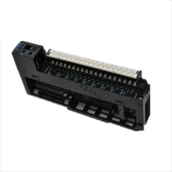
Product Type: 16-Channel Digital Input/Output Module

Product Overview:
The AEG AS-B824-016 is a mixed 16-channel digital I/O module combining 8 inputs and 8 outputs in a single compact unit for PLC integration in industrial automation systems.

Detailed content

Technical Specifications:

  • Total Channels: 16 (8 digital inputs + 8 digital outputs)
  • Input Voltage: 24 V DC (PNP/NPN selectable via DIP switch)
  • Output Voltage: 24 V DC, transistor output, 0.5 A per channel
  • Input Impedance3.3 kΩ (typical)
  • Isolation Voltage: 500 V DC (channel-to-channel, channel-to-bus)
  • Response Time: < 2 ms (input filter), < 1 ms (output switch)
  • Supply Voltage: 24 V DC ± 20%
  • Current ConsumptionMaximum 350 mA from 24 V bus
  • Operating Temperature: -25°C to +70°C
  • Protection Rating: IP20
  • Dimensions: 120 mm x 90 mm x 65 mm
  • Weight250 g

Material Composition:

  • HousingFlame-retardant polycarbonate (UL94 V-0), grey
  • Terminal BlocksPhoenix Contact PSTB 2.5 series, tin-plated brass
  • PCBFR-4, 1.6 mm, HASL finish

Structural Features:

  • DIN rail mounting (35 mm, EN 50022)
  • 8 status LEDs for inputs, 8 status LEDs for outputs
  • DIP switch for PNP/NPN input configuration
  • Spring-clamp terminals for 0.5–2.5 mm² wire
  • Bus connector on rear for backplane communication

Working Principle:
Inputs are optically isolated via photocouplers (PC817 or equivalent). The input state is read by the module’s FPGA and transmitted over the backplane bus to the controller. Outputs are driven by NPN Darlington transistor arrays (ULN2803 or equivalent) with optical isolation from the bus.

Key Advantages:

  • Mixed I/O in one module saves rack space
  • PNP/NPN input selection via DIP switch (no rewiring)
  • Optical isolation on every channel
  • LED diagnostics for every channel

Applicable Industries:
Assembly lines, bottling plants, steel processing, printing presses, textile machinery.

Installation Requirements:

  • Mount on 35 mm DIN rail
  • Wire inputs with 24 V DC PNP or NPN as configured
  • Use 0.5–2.5 mm² stranded wire for terminals
  • Ensure 24 V DC bus power is stable (±20%)

Usage Precautions:

  • Set DIP switch to correct PNP/NPN mode before connecting sensors
  • Do not exceed 0.5 A per output channel
  • Keep away from high-voltage cables (> 500 V)
  • Do not operate above +70°C ambient

You may also like