.jpg "AS-884A-201(1)")

Product Introduction:
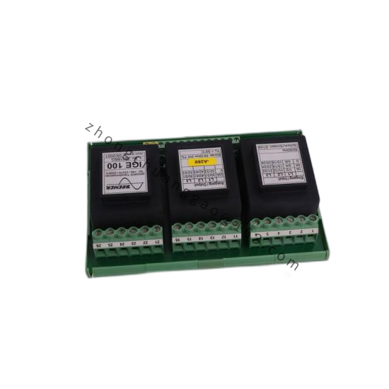
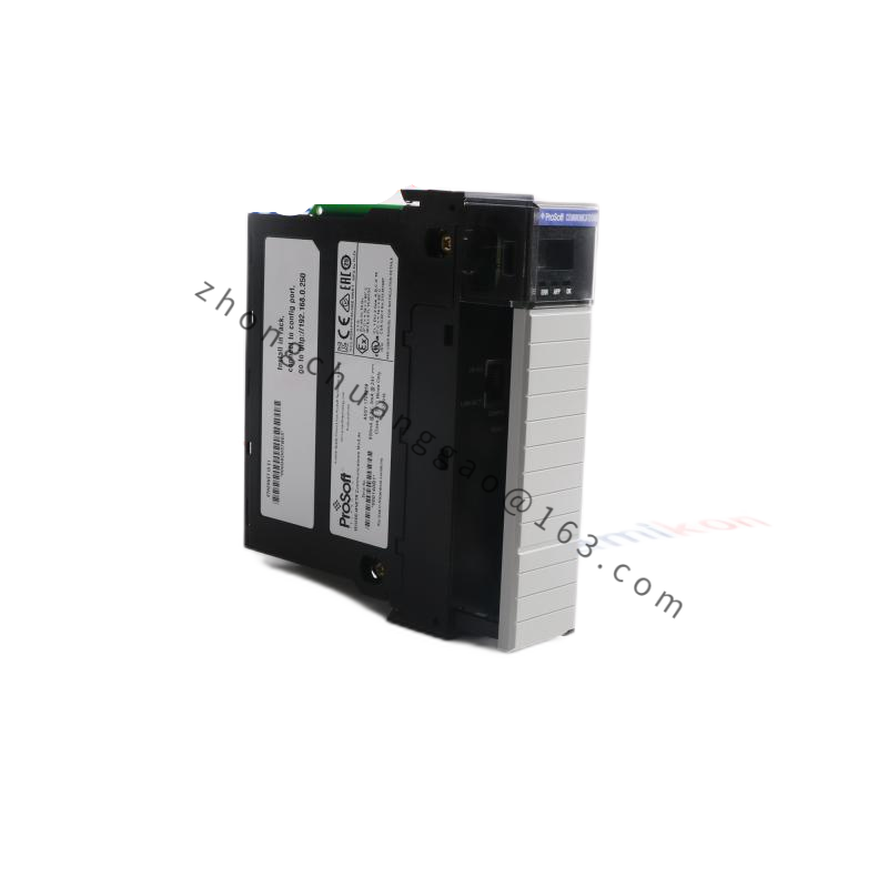
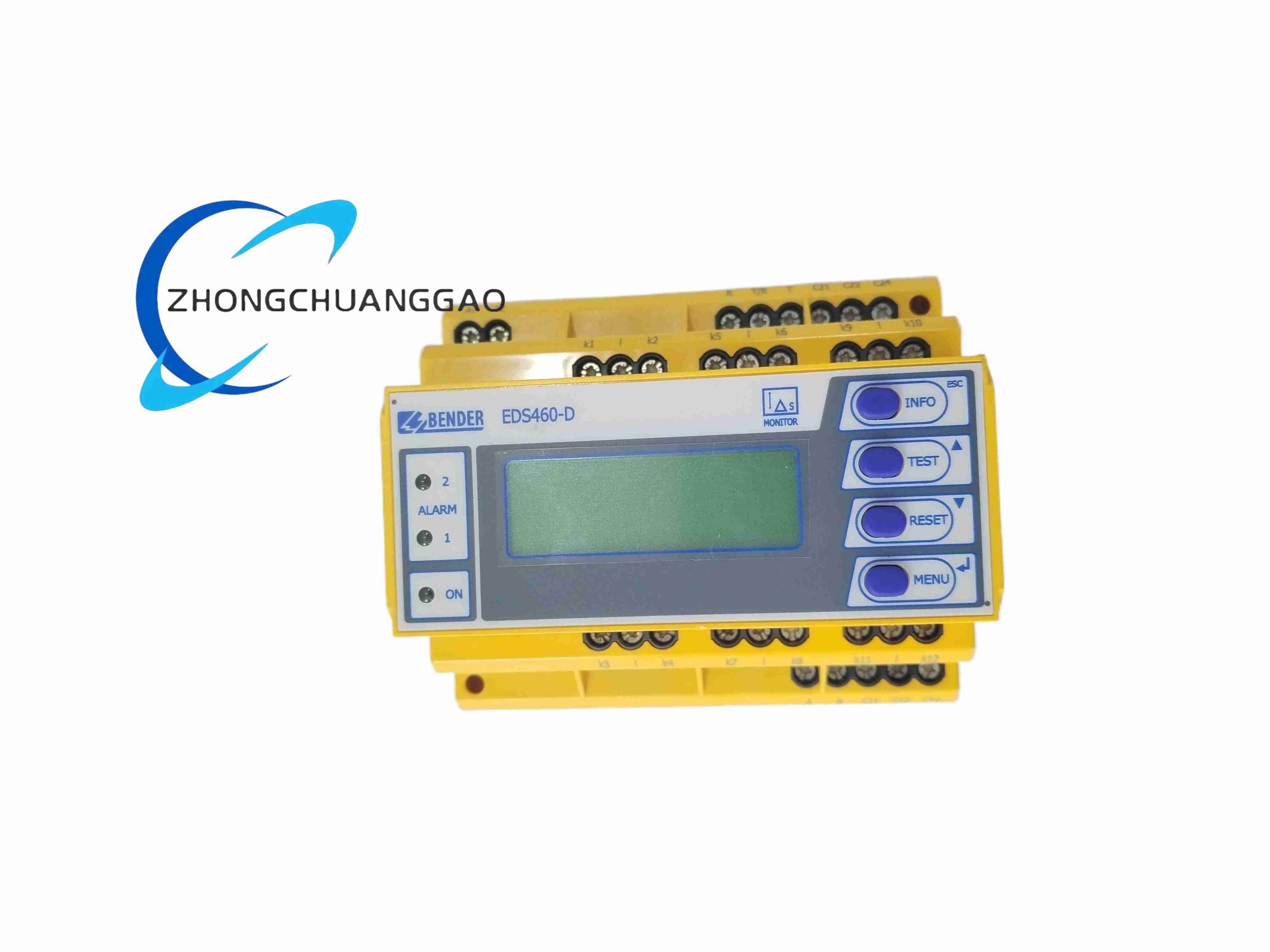
The AEG AM-C916-100 is a motor protection and control relay designed for the monitoring, protection, and switching of three-phase AC motors. It provides comprehensive motor management including overload protection, phase failure detection, under/over-voltage protection, and remote control capabilities. The “100” designation indicates a 100 A rated current capacity.
Technical Specifications:
| Parameter | Value |
|---|---|
| Rated Current (In) | 100 A |
| Rated Voltage (Ue) | 690 V AC (max) |
| Control Voltage (Us) | 24–240 V AC/DC |
| Pole Configuration | 3-Pole (3P) |
| Trip Class | Class 10 (overload), Class 20 (short-circuit) |
| Frequency | 50/60 Hz |
| Auxiliary Contacts | 2 NO + 2 NC (changeover) |
| Standards Compliance | IEC 60947-4-1, IEC 60947-6-2, EN 60947-4-1 |
| Degree of Protection | IP20 (front), IP54 (with cover) |
| Ambient Temperature | -25°C to +60°C |
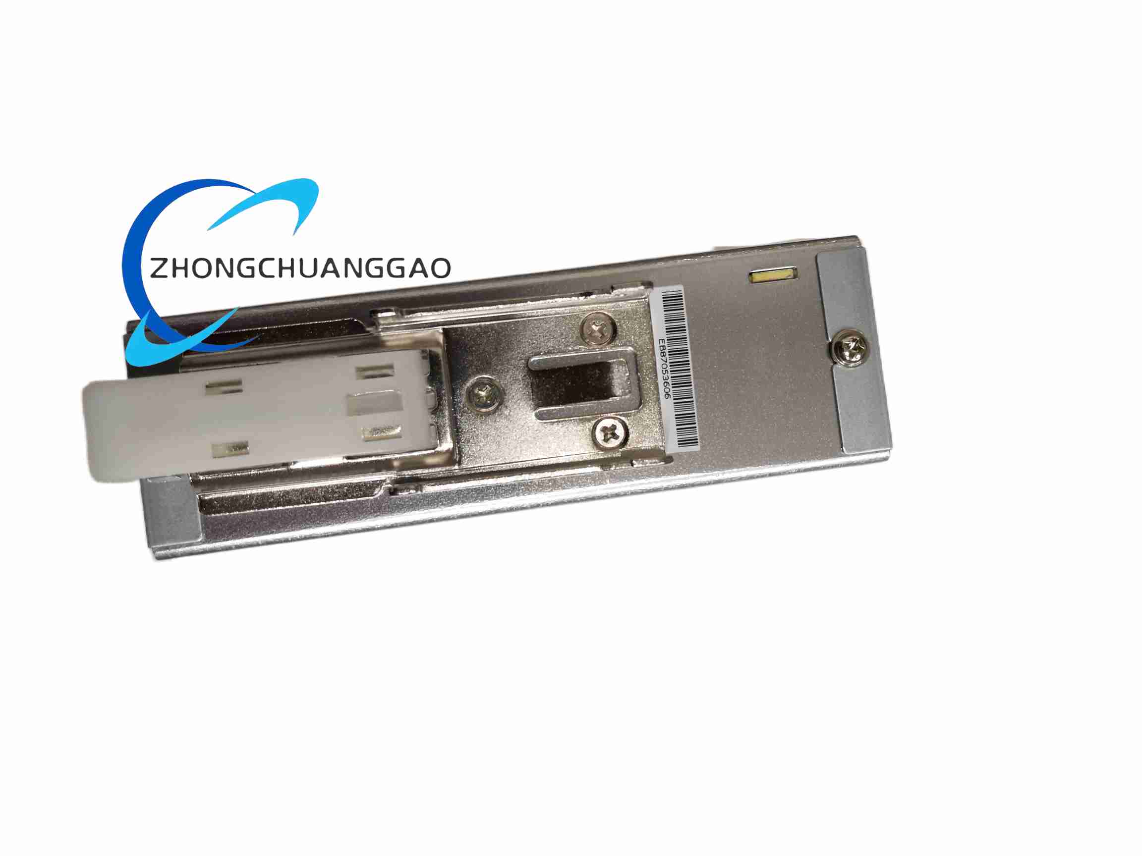
| Mounting | DIN 35 mm rail or screw mounting |
Material Composition:
Structural Features:
Working Principle:
The relay continuously monitors the three-phase motor current via built-in current transformers (CT) or external CTs. The electronic processing unit compares the measured values against user-configurable thresholds. Upon detecting an overload condition, the thermal model calculates the accumulated thermal stress and triggers a time-delayed trip. For phase failure, under-voltage, over-voltage, and phase imbalance, instantaneous or time-delayed trips are executed. The output relay contacts control the contactor coil circuit, disconnecting the motor from the supply.
Functional Features:
Performance Parameters:
| Parameter | Value |
|---|---|
| Overload Trip Accuracy | ±5% at 1.0 × In |
| Short-Circuit Trip Time | < 20 ms at 10 × In |
| Electrical Endurance | 100,000 operations (at rated load) |
| Mechanical Endurance | 1,000,000 operations |
| Response Time (Under-voltage) | < 100 ms |
Advantages & Highlights:
Applicable Industries:
Installation Requirements:
Usage Precautions: