.jpg "PC-E984-685(1)")
AEG 6065-042.244724
Product Category: Appliance Electronic Control Board — Washing Machine / Dishwasher PCB
Product Introduction:
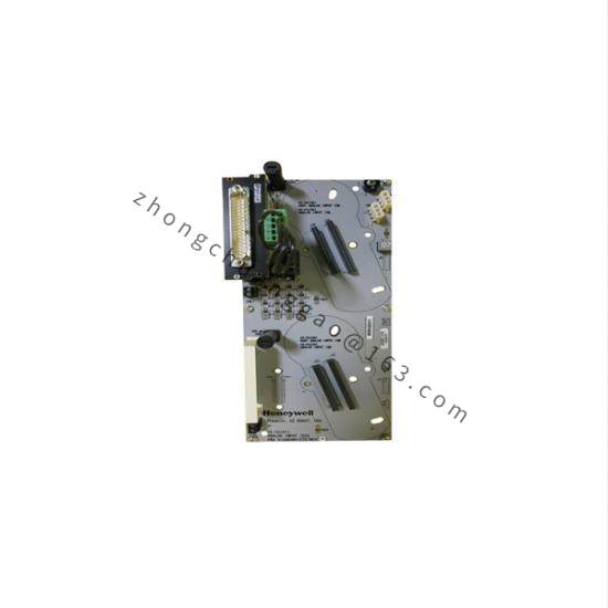
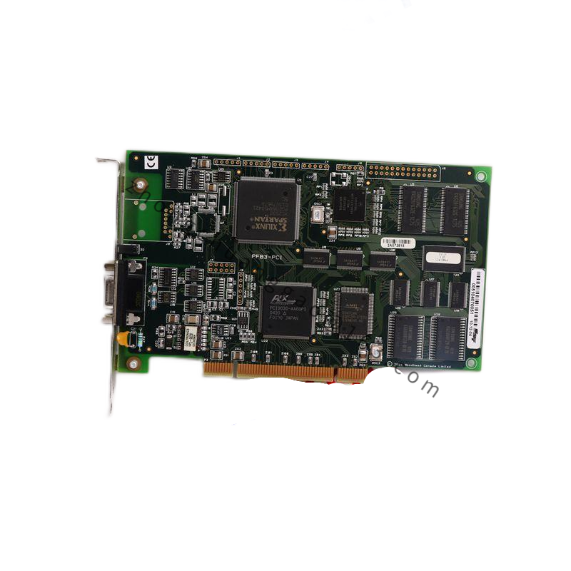
The AEG 6065-042.244724 is an electronic control board (PCB assembly) used in AEG washing machines and dishwashers. It functions as a sub-module or main control board depending on the appliance configuration, handling sensor inputs, actuator outputs, and user interface communication.
Detailed content
Technical Specifications:
- Part Number: 6065-042.244724
- Board Type: Multi-layer PCB (4-layer FR-4)
- Dimensions: Approx. 240 mm × 180 mm × 20 mm
- Microcontroller: 8-bit or 16-bit MCU (AEG proprietary or STM8/STM32 family)
- Operating Voltage (Logic): 5V DC / 3.3V DC
- Operating Voltage (Power Stage): 230V AC (via triac/relay outputs)
- Input Channels:
- NTC temperature sensors × 3 (drum, heater, ambient)
- Door lock switch (2-wire)
- Water level pressure switch
- Tachometer input (Hall sensor or back-EMF)
- Detergent dosing pump interface
- Output Channels:
- Main wash heater relay (16A)
- Drain pump relay (10A)
- Water inlet valve driver × 2 (hot/cold)
- Door lock actuator driver (12V DC)
- Motor speed control (triac or inverter interface)
- Communication: I²C bus (display module), UART (diagnostics)
- Firmware Storage: On-board SPI Flash (256 KB – 1 MB)
- EEPROM: 8 KB (fault log, configuration data)
- Conformal Coating: Yes (acrylic or silicone)
- EMC Compliance: EN 55014-1, EN 55014-2, EN 61000-6-1, EN 61000-6-3
- Operating Temperature: -10°C to +65°C
- Storage Temperature: -40°C to +85°C
Functional Features:
- Full wash/rinse/spin cycle control with programmable timing and temperature ramps.
- Motor speed regulation via triac phase-angle control (universal motor) or PWM (BLDC/inverter motor).
- Water level management using pressure switch input with adaptive fill logic.
- Heater control with over-temperature protection via dual NTC sensor cross-check.
- Door interlock management — prevents operation with open door; enables delayed start.
- Fault code generation and storage — retrievable via service diagnostic tool.
- Detergent dosing pump control — pulse-width modulated output for precise dosing.
- Display panel interface — drives LED/LCD display via I²C or parallel bus.
Material Composition:
- PCB Substrate: FR-4, Tg 155°C, 1.6 mm thickness
- Copper Layers: 2 oz outer layers, 1 oz inner layers
- Surface Finish: ENIG (Electroless Nickel Immersion Gold)
- Solder Mask: Matte green LPI
- Silkscreen: White epoxy ink — component designators and test points labeled
- Connectors: JST XH or Molex KK series, 2.54 mm pitch
- Potting: Silicone gel on high-voltage relay and triac sections
- Test Points: Gold-plated pads for production testing (ICT/FCT)
Structural Features:
- 4-layer stack-up: Signal / Ground / Power / Signal.
- Isolation slots between high-voltage (230V) and low-voltage (5V) sections, ≥ 6 mm clearance.
- Mounting holes: 4× M3 threaded holes for chassis attachment.
- Edge connector: 24-pin or 32-pin for connection to display panel and user interface.
- Water-resistant connector housings with silicone gaskets where wire harnesses enter.
Working Principle:
The MCU executes the appliance firmware stored in SPI flash memory. On power-up, it performs a self-test (POST) checking all sensor inputs and output drivers. It reads the selected program from the user interface, then enters the main control loop:
- Fill phase: Activates water inlet valve(s) via triac/relay; monitors water level via pressure switch.
- Wash phase: Drives motor at programmed speed; activates heater to target temperature via PID control using NTC feedback.
- Rinse phase: Drains via pump relay; refills with fresh water.
- Spin phase: Increases motor speed to maximum RPM; monitors imbalance via tachometer.
- End of cycle: Deactivates all outputs; stores completion status and any fault codes in EEPROM.
The I²C bus communicates with the display module to show time, program status, and error codes. The UART port allows a service technician to connect a diagnostic tool for firmware update and fault reading.
Advantages & Highlights:
- Integrated design — all control functions on a single board, reducing wiring complexity.
- EEPROM fault logging enables accurate diagnosis without oscilloscope.
- Conformal coating protects against humidity, detergent splash, and dust.
- ENIG finish ensures reliable solder joints and long-term corrosion resistance.
- Firmware-upgradable via service UART or I²C bootloader.
Applicable Industries / Use Cases:
- AEG/Electrolux washing machine and dishwasher manufacturing (OEM)
- Appliance repair and aftermarket parts supply
- Electronics contract manufacturing (PCBA)
Compatible Machine Models (Partial List):
- AEG L6 series washing machines
- AEG F5 series dishwashers
- Electrolux EWF, EWT series washing machines
Installation Requirements:
- Install in the designated PCB mounting location inside the appliance chassis.
- Connect all wire harnesses to the correct connectors per the wiring diagram — do not force connectors.
- Secure the board with 4× M3 × 8 mm screws into the chassis standoffs.
- Ensure all connector locks are fully engaged before closing the appliance.
- Perform a full functional test cycle after installation.
Usage Precautions:
- Handle the PCB by its edges only — avoid touching component pads or IC pins.
- Use an ESD wrist strap and grounded work surface during installation.
- Do not expose the board to temperatures above +85°C during storage or operation.
- Verify the firmware version matches the appliance model before installation; reflash using AEG Service Tool if needed.
- If the board is replaced, perform a reset procedure (typically disconnect power for 5 minutes) to clear residual fault codes.
- Store in an anti-static bag at 15–35°C, < 60% RH.