
Digital guide

You are here:

AEG 557VIC12620

Product Introduction:
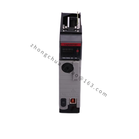
The AEG 557VIC12620 is a mixed-signal I/O module from the Modicon 557 series, specifically configured for voltage input and current output channels. It is designed for process automation applications requiring precise analog signal acquisition and transmission. This module provides high-resolution analog measurement and control capabilities with built-in signal conditioning, isolation, and diagnostics.

Detailed content

Technical Specifications:

  • Module Type: Analog I/O — Voltage Input + Current Output
  • Number of Channels: 8 voltage inputs + 4 current outputs (or configurable mix)
  • Input Signal Range: 0 to 10V DC (configurable: ±10V, 0 to 5V, 1 to 5V)
  • Input Impedance: 500 kΩ minimum
  • Input Resolution: 16-bit (65,536 counts)
  • Output Signal Range: 4 to 20 mA (2-wire, configurable: 0 to 20 mA)
  • Output Resolution: 12-bit (4,096 counts)
  • Accuracy (Input): ±0.1% of full scale (at 25°C)
  • Accuracy (Output): ±0.2% of full scale (at 25°C)
  • Conversion Time: 10 ms per channel (all channels)
  • Isolation: 500V DC channel-to-channel, channel-to-backplane
  • Power Supply: 5V DC from PLC backplane
  • Power Consumption: 2.5 W typical
  • Operating Temperature: 0°C to +60°C
  • Storage Temperature: -25°C to +70°C
  • Dimensions: Standard single-width Quantum module (25.4 mm x 98 mm x 120 mm)
  • Weight: Approximately 0.2 kg

Functional Features:

  • 16-bit resolution for high-precision measurement
  • Software-configurable input ranges (no DIP switches)
  • Burnout detection on current input channels (if applicable)
  • Open-wire detection on all input channels
  • LED per channel for diagnostic status
  • Hot-swap capable (with limited insertion/removal cycles)
  • Calibration via software (zero and span adjustment)

Performance Parameters:

  • Signal-to-Noise Ratio: 86 dB (typical)
  • Common Mode Rejection Ratio (CMRR): 120 dB minimum (at 50/60 Hz)
  • Linearity Error: ±0.05% of full scale
  • Temperature Drift: ±15 ppm/°C (input), ±20 ppm/°C (output)
  • Update Rate: 100 Hz (all channels scanned)

Material Composition:

  • Housing: FR-4 PCB with metal EMI shield can
  • Isolation: Digital isolators (capacitive coupling)
  • Connectors: 32-pin backplane connector + front-panel screw terminals
  • ADC/DAC: 16-bit Sigma-Delta converter (Analog Devices or equivalent)
  • Protection: TVS diodes on all input channels, PTC fuse per channel group

Structural Features:

  • Single-width Quantum module format
  • Front-panel screw terminal blocks (8 inputs + 4 outputs)
  • Channel status LEDs (green = normal, amber = warning, red = fault)
  • Backplane connector with keyed alignment
  • Removable terminal cover for maintenance

Working Principle:
Analog input signals are fed to the module’s multiplexer, which sequentially routes each channel to a 16-bit Sigma-Delta ADC. The ADC converts the analog voltage to a digital value, which is scaled and stored in the input register. The PLC CPU reads these values via the backplane bus. For output channels, the CPU writes digital values to the output register, which are converted by a 12-bit DAC to a proportional 4–20 mA current signal, driven by a precision current loop transmitter. Channel-to-channel and channel-to-backplane isolation is maintained via capacitive digital isolators.

Advantages & Highlights:

  • High Resolution: 16-bit input resolution for precise measurement
  • Flexible Configuration: Software-configurable ranges — no hardware changes
  • Built-In Diagnostics: Per-channel LEDs and burnout/open-wire detection
  • Galvanic Isolation: 500V isolation protects PLC from field transients
  • Wide Temperature Range: 0°C to +60°C for harsh environments

Applicable Industries:

  • Process control (temperature, pressure, flow, level)
  • Chemical and petrochemical plants
  • Food and beverage processing
  • Pharmaceutical manufacturing
  • Water treatment plants
  • HVAC systems

Installation Requirements:

  • Mount in Quantum PLC chassis (single-width slot)
  • Use shielded twisted-pair cable for analog signals
  • Connect voltage inputs with shield grounded at PLC end only
  • Current output loops must be powered by external 24V DC supply
  • Maximum cable length: 100 m for voltage input, 300 m for current output
  • Separate analog cables from digital/power cables (minimum 100 mm)

Usage Precautions:

  • Do not apply voltage exceeding 30V DC to input channels
  • Do not open current output loop while powered (damage to output stage)
  • Calibrate after installation and annually thereafter
  • Use proper cable shielding to avoid noise pickup
  • Verify input range configuration matches field transmitter output

You may also like