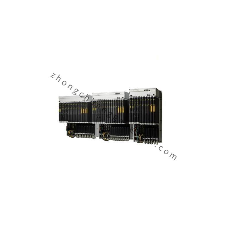

Product Introduction:
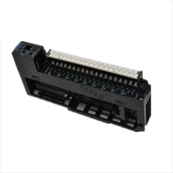
The AEG 110-CPU-612-03 is a CPU module for the AEG Series 110 PLC platform. It is the central processing unit that executes the user program, manages I/O communication, and controls the overall operation of the PLC system. The “110” denotes the series, “CPU” identifies it as the processor, “612” specifies the memory/performance variant, and “03” is the hardware revision.
Technical Specifications:
| Parameter | Value |
|---|---|
| Model | 110-CPU-612-03 |
| Series | AEG Series 110 PLC |
| CPU Type | 16-bit / 32-bit microprocessor |
| Program Memory | 128 KB (typical for 612 variant) |
| Data Memory | 64 KB RAM (battery-backed) |
| User Memory | 32 KB (non-volatile) |
| Digital I/O Points | Up to 256 DI + 256 DO (dependent on rack configuration) |
| Analog I/O Channels | Up to 32 AI + 16 AO (dependent on modules) |
| Communication Ports | RS-485, RS-232, Ethernet (optional module) |
| Processing Speed | 0.1 µs per basic instruction |
| Program Scan Time | < 10 ms for 1K steps |
| Operating Voltage | 24 V DC (nominal), 20.4–28.8 V DC range |
| Power Consumption | < 5 W (typical) |
| Standards Compliance | IEC 61131-3, IEC 61131-2, EN 61131-2, UL 508 |
| Degree of Protection | IP20 (front), IP40 with cover |
| Ambient Temperature | 0°C to +55°C (operating), -25°C to +70°C (storage) |
| Mounting | DIN 35 mm rail or backplane bus (Series 110 rack) |
| Firmware Revision | 03 (hardware revision 03) |
Material Composition:
Structural Features:
Working Principle:
The CPU module continuously executes the user program stored in non-volatile memory in a cyclic scan: (1) Input Scan → reads all input module states into the process image input (PII); (2) Program Execution → processes the ladder logic/function block/structured text program using the PII; (3) Output Scan → writes results to the process image output (PIO) and updates all output modules. The scan cycle repeats continuously. Communication with programming devices (PC) and HMI panels occurs via RS-232/RS-485 or Ethernet. The battery-backed RAM retains the program and data when power is removed.
Programming Languages (IEC 61131-3):
Functional Features:
Performance Parameters:
| Parameter | Value |
|---|---|
| Boolean Instructions | 0.1 µs per instruction |
| Integer Math (ADD/SUB) | 0.5 µs |
| Floating Point Math | 5 µs |
| High-Speed Counter Input | Up to 100 kHz |
| Pulse Output Frequency | Up to 50 kHz |
| Communication Baud Rate | 9600–115200 bps (RS-485) |
Advantages & Highlights:
Applicable Industries:
Installation Requirements:
Usage Precautions: