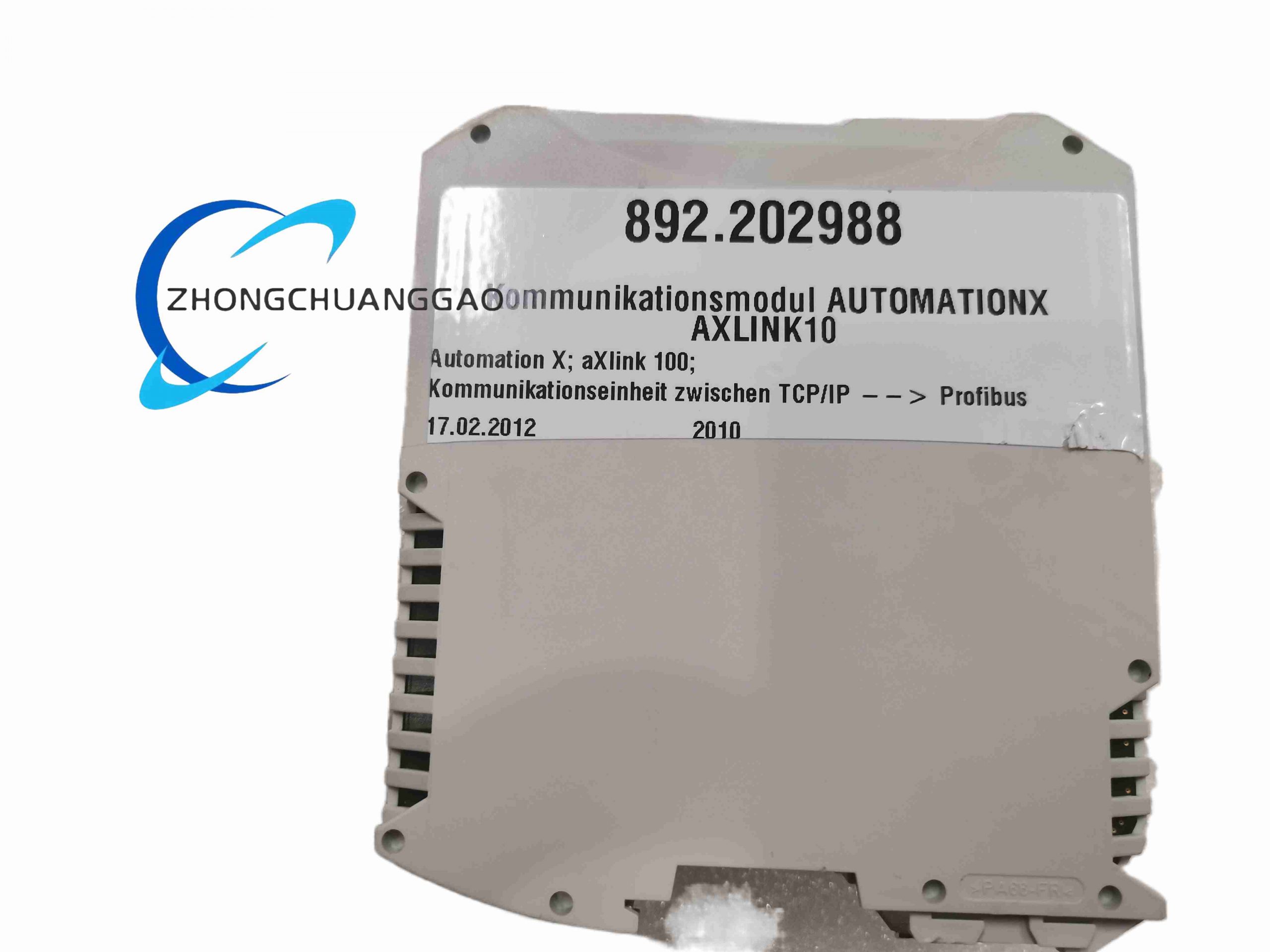
Technical Specifications: The Ethernet–PROFIBUS variant provides two 10/100 Mbit/s RJ45 Ethernet ports or an optional fiber interface and one PROFIBUS-DP master port on 9-pin Sub-D. PROFIBUS speed reaches 12 Mbit/s. Supply voltage is 14–30 V DC, typical consumption 0.15 A average and 8.2 W peak. The optical remote-I/O variant provides two ST multimode ports, 2.5 Mbit/s deterministic traffic, 32 remote nodes per ring and up to 2 km per segment with 62.5/125 µm fiber.
Functional Features: The unit supports XLink real-time Ethernet, PROFIBUS-DP master communication, redundant Ethernet ring or star topology, self-healing optical ring operation, front status LEDs, programmable addresses and diagnostic reporting.
Performance Parameters: One gateway supports up to 124 PROFIBUS-DP slaves in the PROFIBUS configuration. Sixteen AXLINK100 units can be linked to one AutomationX station in large networks. Optical configuration provides galvanic isolation and immunity to electromagnetic interference.
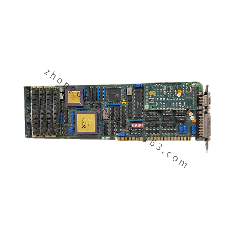
Material Composition: The enclosure uses industrial-grade metal and plastic. Internal assemblies include optical transceivers or Ethernet PHY chips, PROFIBUS ASIC, processor, RAM, flash memory and isolated power stages.
Structural Characteristics: The module is DIN-rail mountable with RJ45, fiber ST or Sub-D connectors, LED indicators for power, link, bus and faults, and removable power terminals where fitted.
Working Principle: Ethernet frames or XLink real-time packets are converted to PROFIBUS-DP messaging, or optical ring frames are forwarded to the controller backplane. The module maintains cyclic data, diagnoses link quality and switches to redundant paths on cable or node failure.
Installation Requirements: Install on a clean DIN rail inside the control cabinet. Use shielded Cat5e or better for RJ45, 62.5/125 or 50/125 µm multimode fiber for ST ports, and properly terminated PROFIBUS cable with 9-pin Sub-D connectors. Supply stabilized 24 V DC with fuse protection.
Usage Precautions: Confirm the ordered variant before commissioning because Ethernet–PROFIBUS gateways and optical remote-I/O links use different firmware. Keep both ring ports active in redundant systems. Inspect optical power, temperature and bus error counters during preventive maintenance.


.jpg)
.jpg)
.jpg)

