Technical Specifications
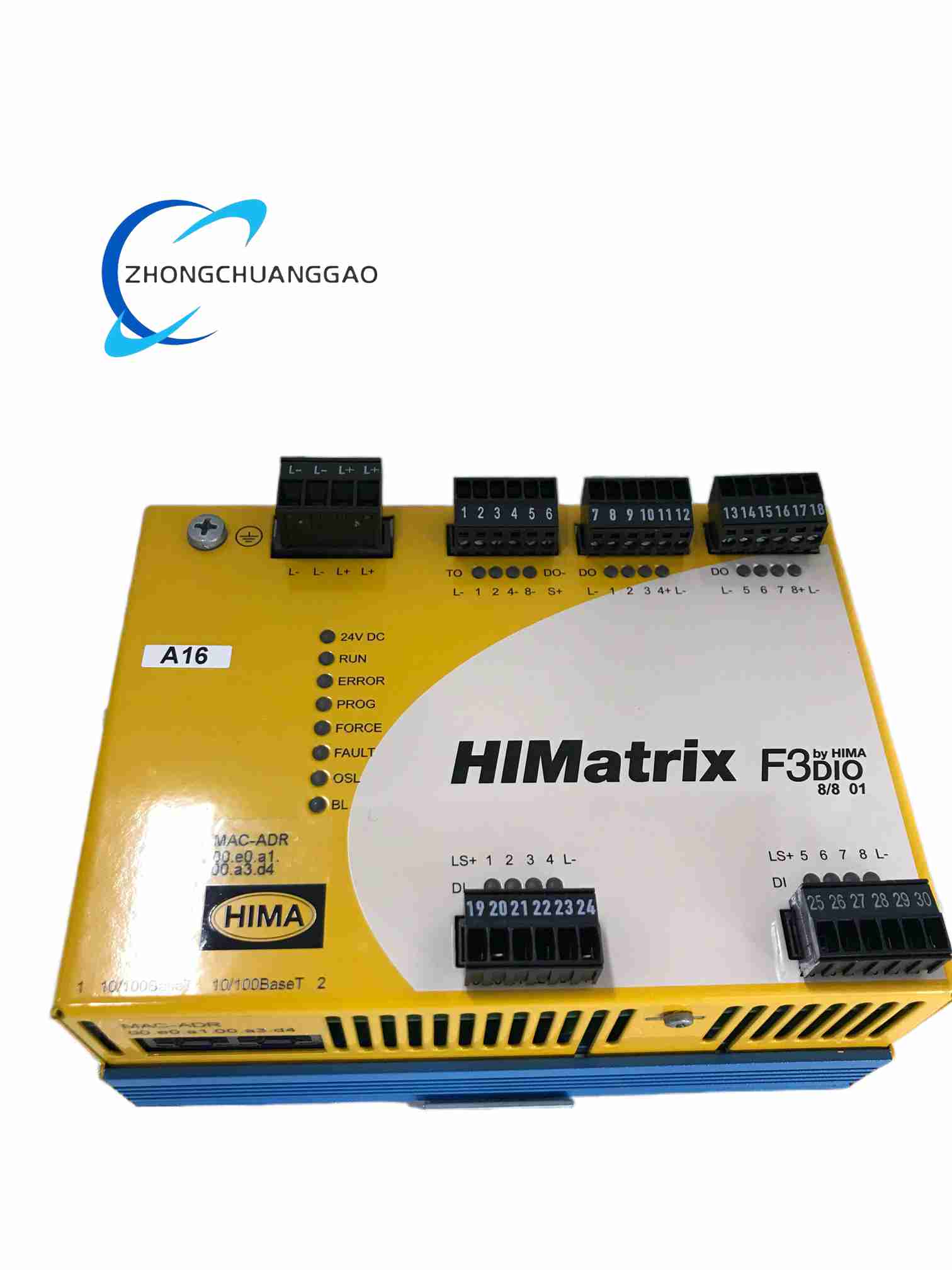
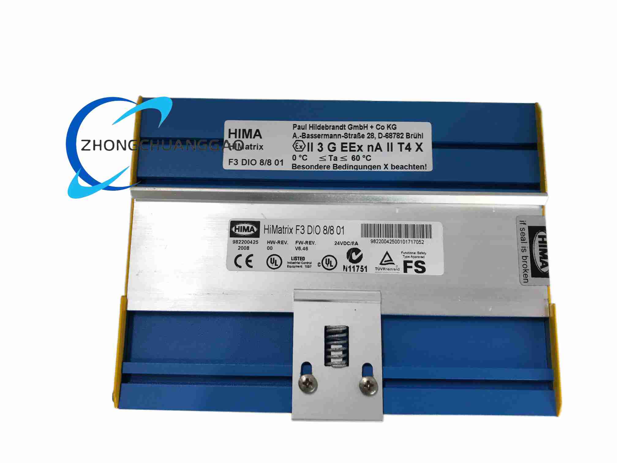
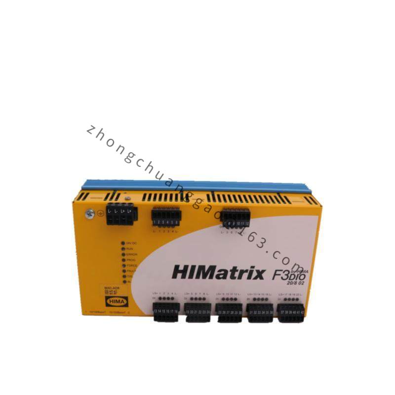
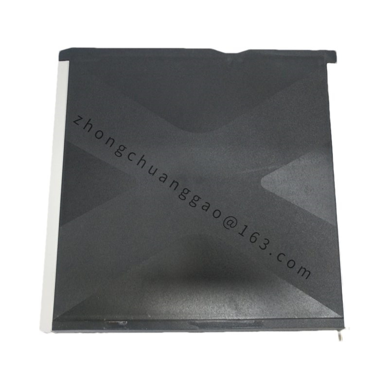
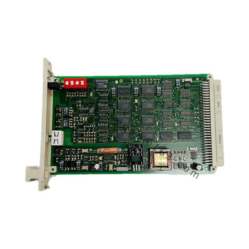
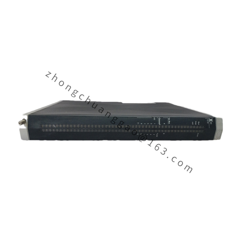
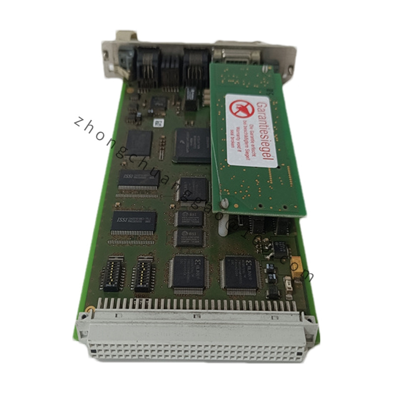
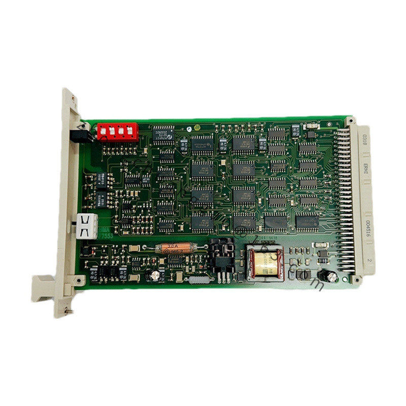
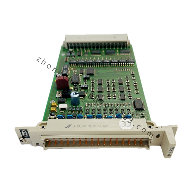
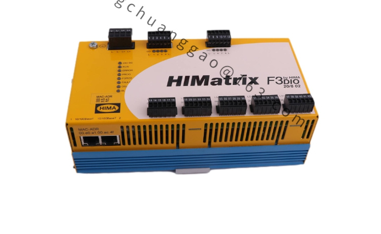
8 safety-related digital inputs; 8 digital outputs with DO+/DO− types plus 2 pulse outputs. Supply 24 V DC. LEDs indicate operating voltage, system status, communication and I/O status. Nameplate carries product name, barcode, part number (e.g., 982200425), year of manufacture, HW revision, FW revision, operating voltage and conformity marks.
Diagnostics & Safety Functions
The front-panel fault LED flashes and a diagnosable error code is generated, with inputs forced low, when faults such as cross-circuits between parallel lines, incorrect wiring (e.g., TO2 to DI3), ground faults, or open circuits/open contacts occur. This supports reliable detection of wiring errors and field faults in emergency-stop circuits.
Application Scenarios
Emergency shutdown systems, fire & gas detection, machine safety and protective guarding, turbine and compressor protection, process interlocks, and any SIL-rated application requiring monitored digital inputs and safely driven outputs.
Installation Requirements
Wire DO+/DO− according to the required actuator topology (solenoid valves, relays, contactors) and observe the load rating per channel; implement cross-circuit-safe cabling (separate cores/conduits) so that the module’s diagnostics remain effective; integrate into the SafeEthernet network per the HIMA plan; configure and validate in SILworX/ELOP II; comply with IEC 61508/IEC 61511 and the project SRS.
Precautions
Do not bypass the dual-channel/monitored wiring concept—doing so defeats the diagnostic coverage; verify proof-test intervals and diagnostic reaction times in the project documentation; check HW/FW revision against the approved system configuration; keep within the specified ambient conditions (standard 0 °C to +60 °C, −20 °C variant where applicable).