Technical Specifications
Host compatibility: Allen-Bradley 1336 FORCE AC drive family.
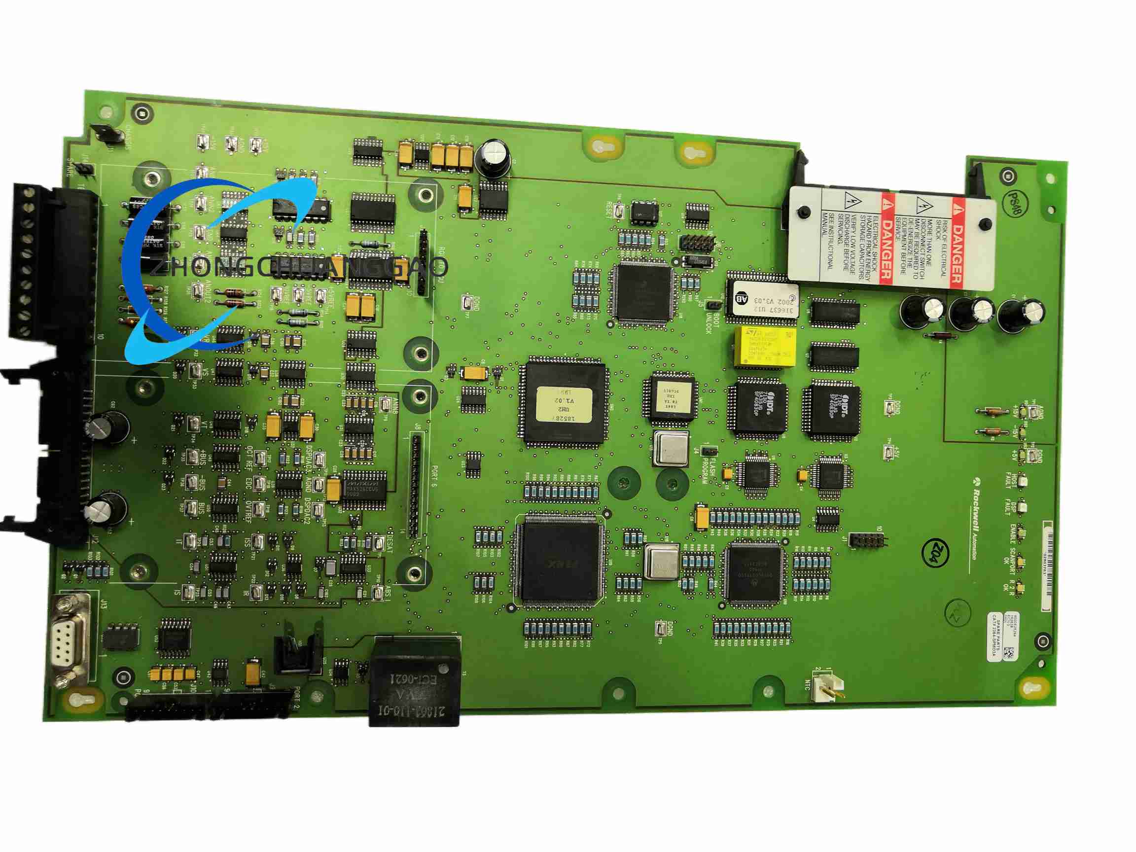
Component type: integrated SPM, internal service part module.
Electrical rating: derived from drive DC bus and control supply; standalone third-party listings publish 3 kW output, 560 VDC bus, 380 VAC to 480 VAC three-phase input for servo-power configurations.
Protection form: open type, IP00 for internal chassis installation.
Mounting: internal chassis/module mount within drive frame.
Cooling: chassis forced-air or drive-duct cooling depending on host frame.
Functional Features
Distributes DC bus power to drive power stages.
Routes gate-drive and feedback signals to IGBT/modules.
Supports drive diagnostics through main control board.
Provides regenerative and braking energy management in servo-power configurations.
Includes overvoltage, overcurrent, and overtemperature protection in power-module configurations.
Material Composition and Structure
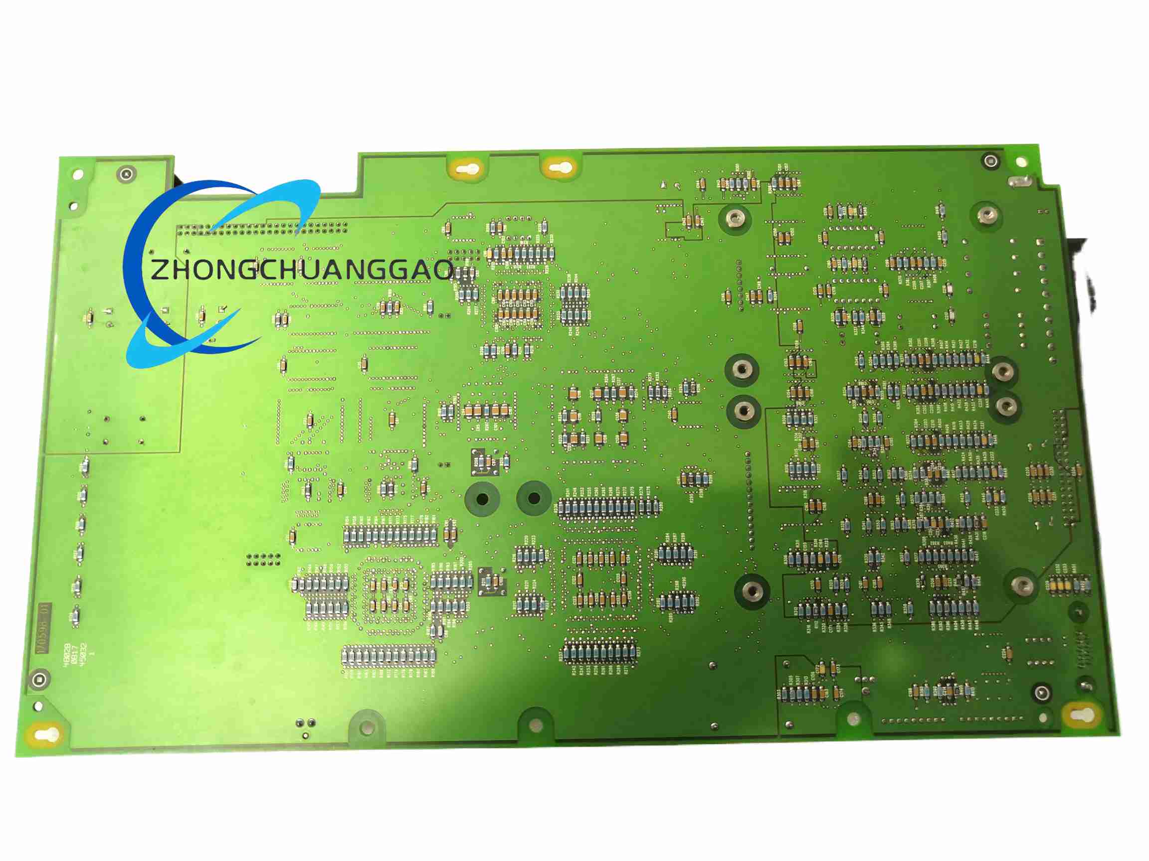
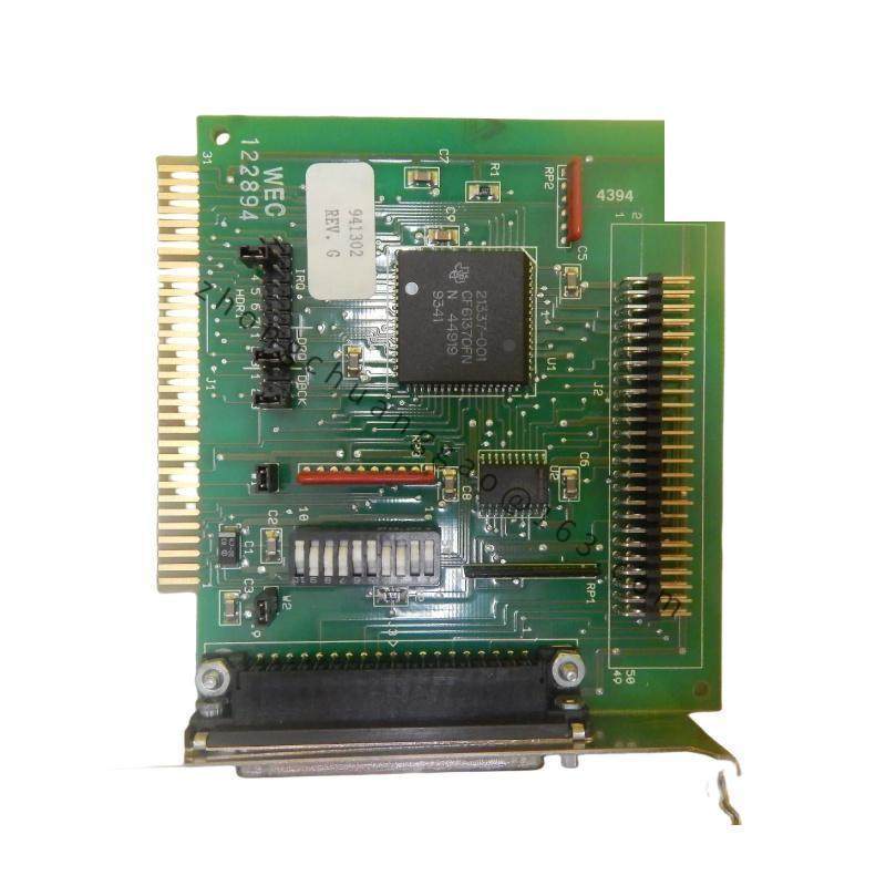
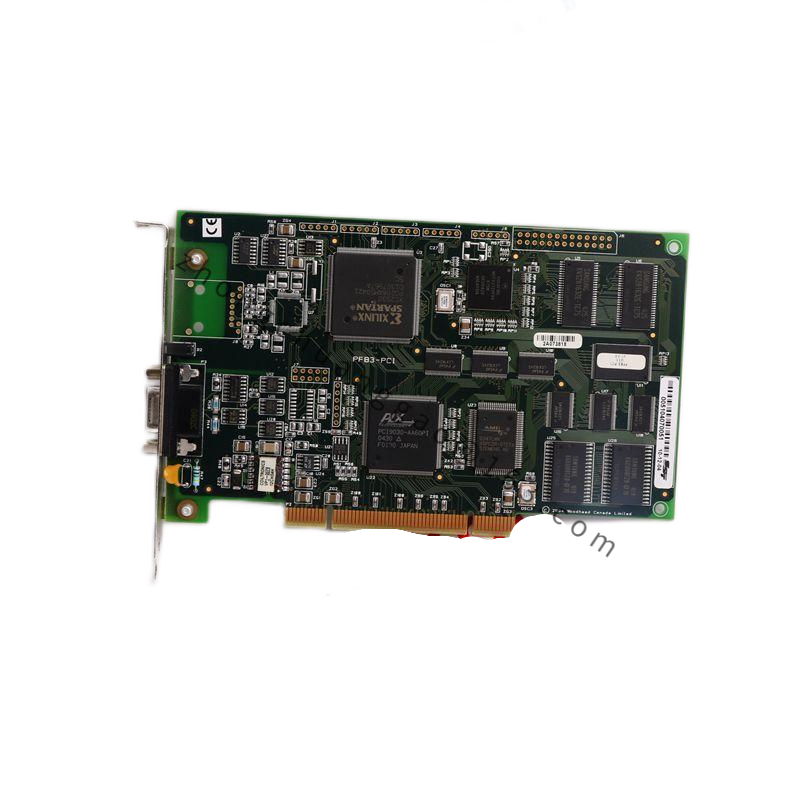
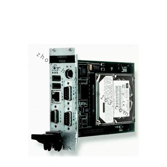
Industrial printed circuit assembly with power semiconductors, copper bus bars, insulated mounting hardware, and aluminum heat dissipating structure where used as power module. Enclosed in drive chassis; no独立 field enclosure.
Working Principle
AC input is rectified to a regulated DC bus. The module distributes bus voltage to inverter stages and transfers low-voltage gate commands from the controller to power devices. Diagnostic signals are returned to the main processor for fault monitoring and protection coordination.
Installation Requirements
Install only inside the matching 1336 FORCE frame. Disconnect all drive power and wait for DC-bus capacitors to fully discharge. Seat the module on its backplane connectors and secure mounting hardware. Verify gate, feedback, and power cabling before re-energizing.
Usage Notes
Use exclusively with the qualified 1336 FORCE configuration. Do not install in 1336 PLUS, PLUS II, or unrelated drive families. Perform insulation and continuity checks before power-up. Follow lockout/tagout and high-voltage safety procedures.