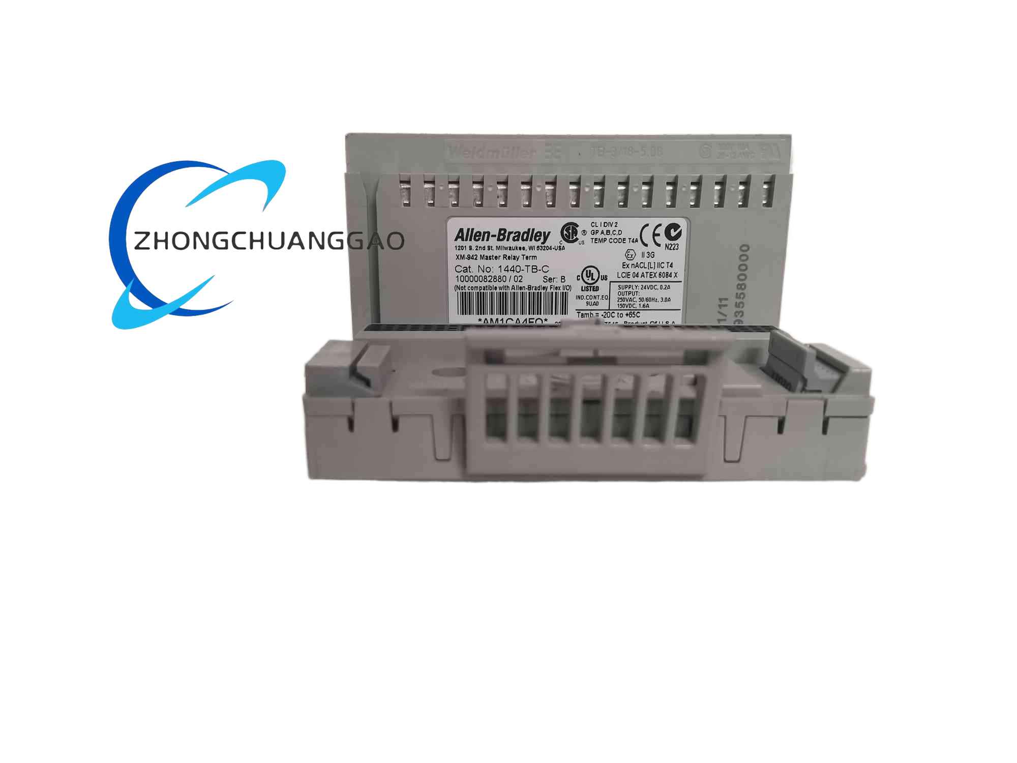
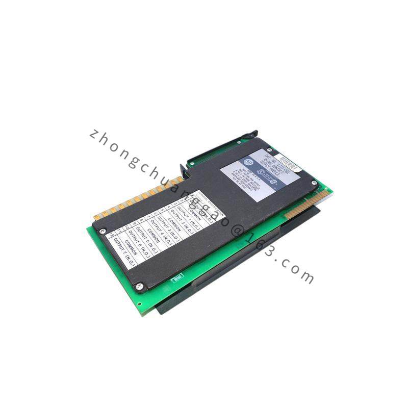
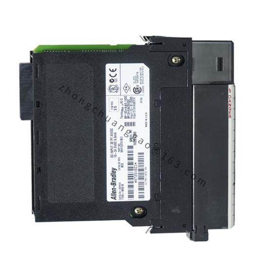
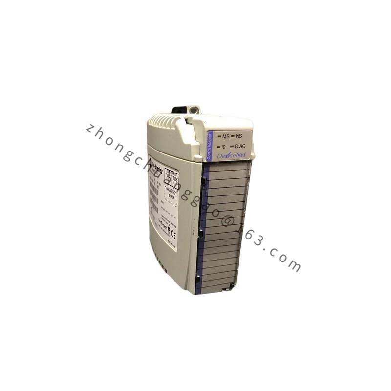
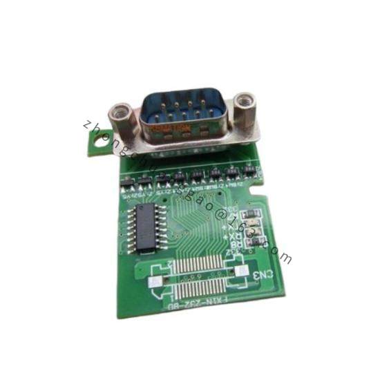
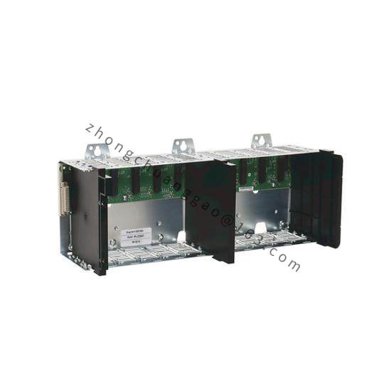
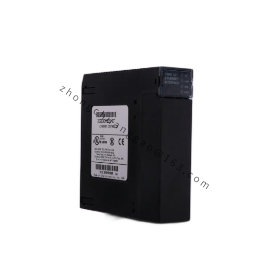
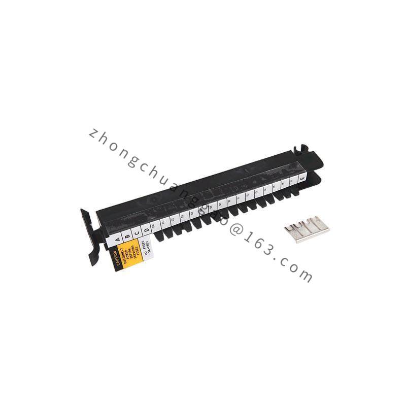
Technical Specifications: Compatible module family is Allen-Bradley XM 1440 measurement modules, especially 1440-xx-01RB types. Terminal style is H-type screw clamp. Side interconnection current must not exceed 3 A total. XM power wiring support includes up to 100 W output, approximately 4 A at 24 VDC, static regulation ±2%, dynamic regulation ±3%, ripple below 100 mVpp. Acceptable wire is solid or stranded; follow each mounted module’s voltage, current and sensor-range ratings.
Functional Features: Fixed mechanical seating for XM modules, reliable screw-clamp termination, compact panel footprint, direct integration with XM controllers and Logix condition-monitoring workflows, simple spare-module replacement without rewiring harness redesign.
Application Scenarios: Rotating-equipment vibration monitoring, pump and compressor condition-based maintenance, turbine and motor temperature/pressure signal termination, factory predictive-maintenance systems, process skids requiring localized machinery instrumentation.
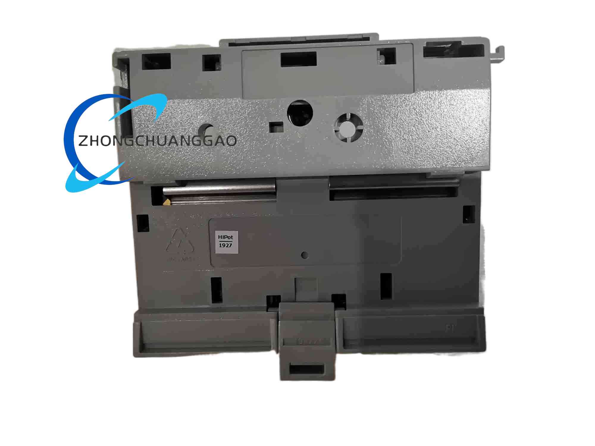
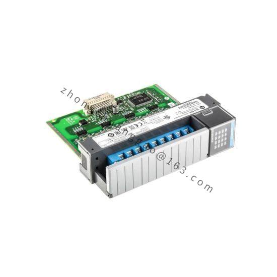
Materials and Structure: Industrial terminal base with screw-clamp contacts, molded insulating body, XM rail adapter and side bus connector. The H-terminal arrangement separates sensor input, module power and bus communication paths.
Working Principle: The measurement module plugs into the base and receives conditioned sensor signals through screw terminals. The base transfers power and inter-module communication through the side connector while field wires remain fixed. The connected XM module processes waveform, RMS, temperature or pressure values and forwards results to the control system.
Installation Requirements: Mount on the XM rail or designated XM enclosure position. Seat the 1440 measurement module until locked. Use properly stripped solid or stranded conductors in the H screw terminals. If total interconnected module current exceeds 3 A, add a separate power tap near the center of the row. For fused supplies, use the specified Allen-Bradley fuse kit and rating.
Usage Precautions: Do not exceed 3 A through the side interconnect. De-energize the XM power supply before replacing modules. Verify torque and wire size for vibration sensor signal levels. Keep low-level sensor wiring separated from power conductors to prevent ground-loop noise.